Automatic compression release mechanism

A mechanical device and automatic technology, applied in the direction of valve device, mechanical equipment, engine components, etc., can solve problems such as fragile, variable weight shaft holding force, and long shaft

Inactive Publication Date: 2005-09-28
KOHLER CO
View PDF0 Cites 0 Cited by
  • Summary
  • Abstract
  • Description
  • Claims
  • Application Information

AI Technical Summary

Problems solved by technology

Thus, retention of the counterweight shaft on this cam arrangement can become problematic
In particular, a shackle or other simple means of attaching to the end of the shaft to hold the shaft in position relative to the cam arrangement c

Method used


Image

  • Automatic compression release mechanism
  • Automatic compression release mechanism
  • Automatic compression release mechanism

Examples


Embodiment Construction

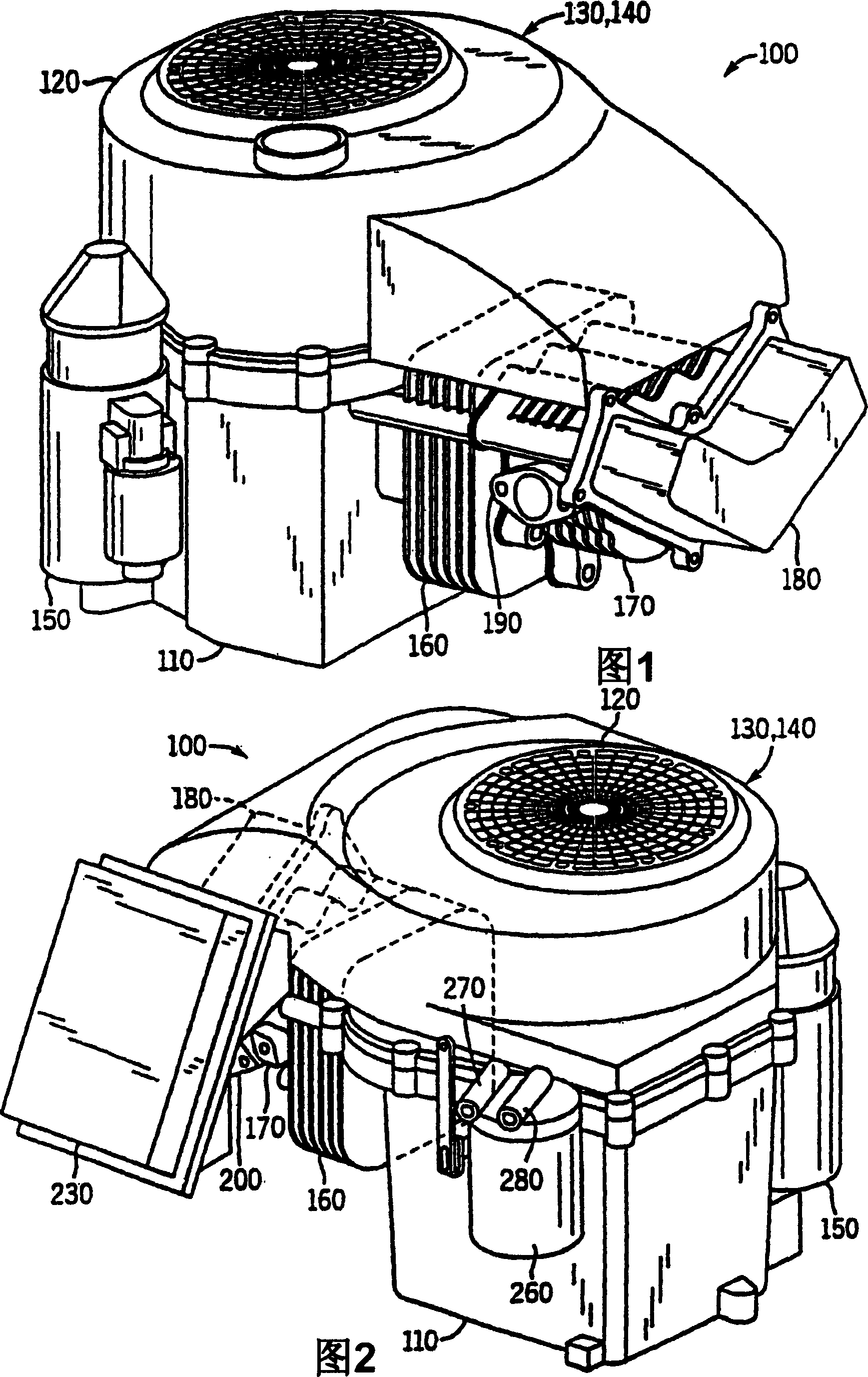
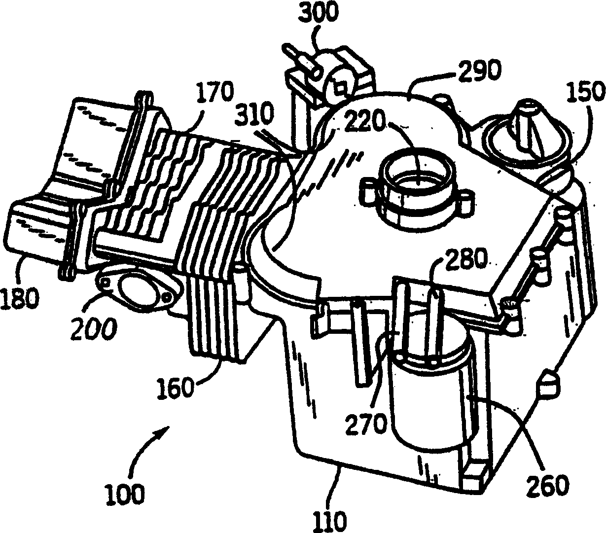
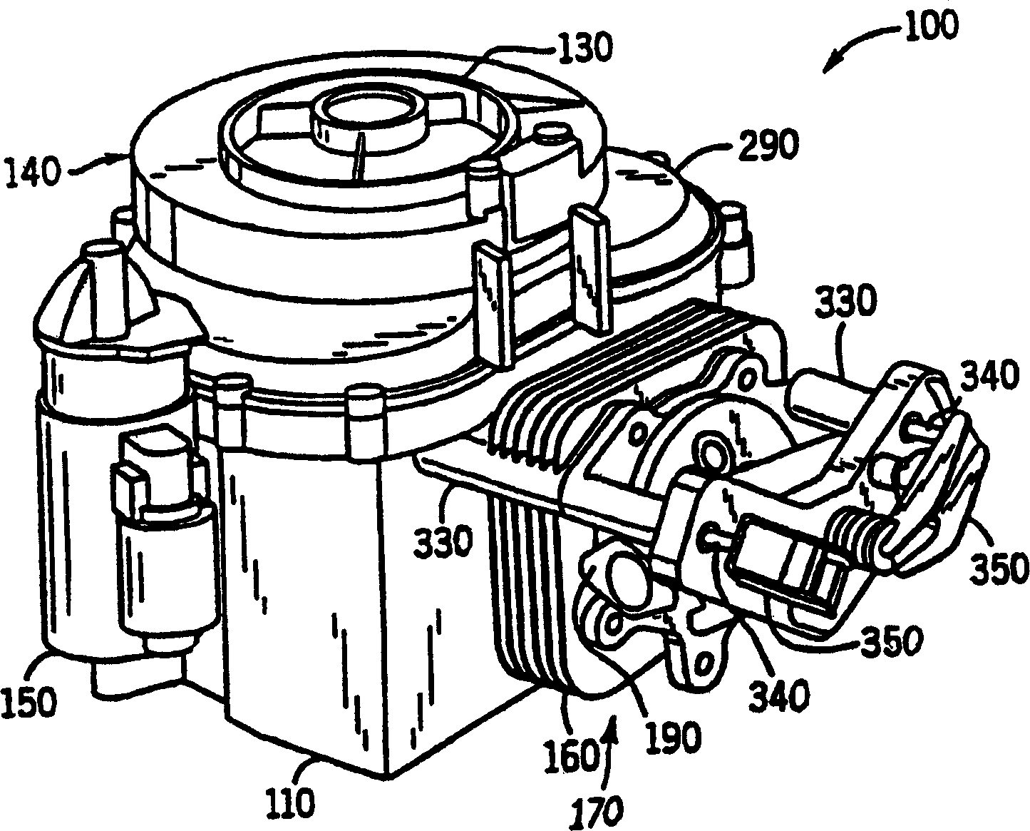
[0021] 1 and 2, a new type of single-cylinder, 4-stroke engine 100 designed by Kohler Corporation of Kohler, Wisconsin includes a crankcase 110 and a blower housing 120. Inside the blower housing 120, there are a fan 130 and a flywheel 140. The engine 100 also includes a starter 150, a cylinder 160, a cylinder head 170, and a rocker cover 180. On the cylinder head 170 are the exhaust port 190 shown in FIG. 1 and the intake port 200 shown in FIG. 2. As known in the art, during the operation of the engine 100, the piston 210 (see FIG. 7) moves back and forth in the cylinder 160 toward and away from the cylinder head 170. The movement of the piston 210 in turn causes the rotation of the crankshaft 220 (see FIG. 7), and the rotation of the fan 130 and the flywheel 140 connected to the crankshaft. The rotation of the fan 130 cools the internal combustion engine, while the rotation of the flywheel 140 causes a relatively constant rotational momentum to be maintained.

[0022] Referring ...


PUM


Abstract

An automatic compression release mechanism for implementation in an internal combustion engine, and a method of assembling such a mechanism, are disclosed. The mechanism includes a camshaft assembly including a cam gear (320), a cam lobe (360) with a notch positioned along a first side of the gear (320), a tube (550) passing through the gear (320) and aligned with the notch (580), and a support on a second side of the gear. The mechanism additionally includes an arm (510) including a weight (530) and shaft (540) coupled to one another, where an end of the shaft (540) includes a recess (620), and where the shaft is rotatably positioned within the tube and the end of the shaft with the recess extends into the notch. The mechanism further includes a retaining member positioned onto the support so that the weight is positioned between the retaining member and the tube and retained with respect to the gear.

Description

Technical field [0001] The present invention relates to internal combustion engines, and more particularly to automatic compression and release mechanical devices used in internal combustion engines. Background technique [0002] Automatic compression and release mechanisms are used in internal combustion engines to improve engine performance at various engine speeds. Such a mechanical device typically includes a component driven based on the speed of the internal combustion engine, which continuously changes the characteristic outer surface of the cam lobe, and a push rod controls the exhaust valve of the engine along the cam lobe. Specifically, when the engine is at a low speed, such as during the start of the engine, a protrusion is generated on the cam lobe so that the exhaust valve tends to open slightly during the compression stroke of the engine, which facilitates the engine Start. However, when the engine is at a higher speed, such as during normal operation of the engine...

Claims


Application Information

Patent Timeline
IPC IPC(8): F01L13/08
CPCF01L13/085
Inventor K·G·邦迪R·W·理查德
Owner KOHLER CO
Why Eureka
Try Eureka