

Controlling system and method for long-range remote-controlled high-voltage switch
A high-voltage switch and remote control technology, which is applied in the transmission system, digital transmission system, electrical components, etc., can solve the problems of large investment in signal transmission lines, large daily maintenance, and short remote control distance, so as to save network construction investment and prolong The effect of short life cycle and delay
- Summary
- Abstract
- Description
- Claims
- Application Information
AI Technical Summary
Problems solved by technology
Method used
Image

Examples
Embodiment 1
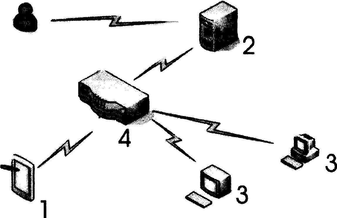
[0047] Embodiment 1, a kind of high voltage remote control switch control system of this embodiment, its structure can be from figure 2 As seen in the figure, it includes a control terminal 1, an address server 4, a server 2, and a plurality of execution terminals 3. The control terminal 1 is a computer, and the connection between it and the address server 4 is realized through the Internet. The connection between the control terminal 1 and the execution terminal 4 is: to activate the execution terminal by sending a short message from the control terminal to the execution terminal, the execution terminal is connected to the GPRS network, and then the server transmits the control command to the execution terminal for execution. The single-chip microcomputer of the execution terminal is connected with the high-voltage switch through the switch controller (see Figure 6 ), the switch controller is a component located between the high-voltage switch and the CPU module of the exec...
Embodiment 2
[0064] Embodiment 2. The difference between this embodiment and Embodiment 1 is that the server distinguishes the execution terminals. While opening a different TCP port communication for each execution terminal, assign a different ID number to each execution terminal, and Create an ID table in the central server database, and update the ID in time, and send this ID number at the same time when sending data to achieve.
[0065] When each execution terminal is connected to the server, a different port is used, and the port allocation table is reserved on the server, and the ID number is extracted from the information obtained from the specific port, so that the identity of the execution terminal can be verified twice to achieve accurate positioning and execution terminal.
[0066] In this embodiment, in the whole control process, only the control terminal wakes up the execution terminal and activates by text message, while the transmission of other data or commands adopts GPRS ...
Embodiment 3
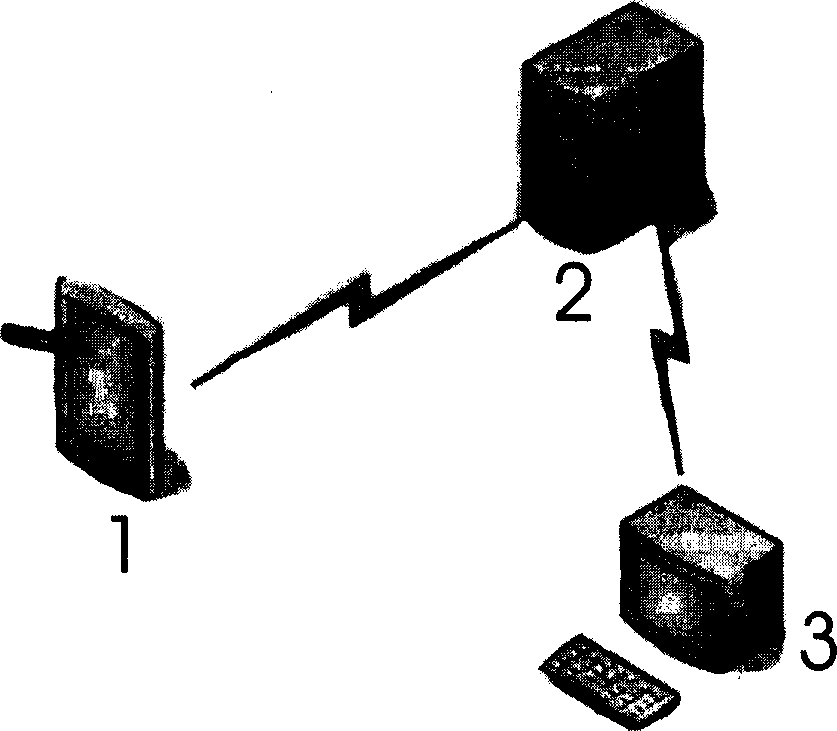
[0067] Embodiment 3, this embodiment sees figure 1 , is stand-alone control mode, has an execution terminal, and the structure of execution terminal and server is identical with embodiment 1, and the control terminal 1 of present embodiment adopts special-purpose mobile phone, is about to put each component module of control terminal in a special-purpose mobile phone, and mobile phone sends short message The execution terminal is activated by the server 2, the execution terminal 3 is verified and connected to the Internet, and the dedicated mobile phone is also connected to the Internet through GPRS. The dedicated mobile phone sends the command to be executed to the execution terminal. After the execution terminal executes the command, the execution result is simultaneously Send it to the server and the dedicated mobile phone, then disconnect the Internet and automatically enter the dormant state.
PUM
 Abstract
Description
Claims
Application Information