Coding of information in integrated circuits

A circuit and coding technology, applied in the field of information coding in integrated circuits, can solve problems such as crosstalk

Inactive Publication Date: 2005-10-12
III HLDG 6
View PDF1 Cites 2 Cited by
  • Summary
  • Abstract
  • Description
  • Claims
  • Application Information

AI Technical Summary

Problems solved by technology

[0005] Having to add dedicated hardware to an IC for the sole purpose of eliminating crosstalk is a drawback, especially when considering that ever-increasing integration densities on ICs will cause crosstalk to occur more significantly and also increase the required additional hardware, which has a negative impact on the silicon cost of the IC

Method used


Image

  • Coding of information in integrated circuits
  • Coding of information in integrated circuits
  • Coding of information in integrated circuits

Examples


Embodiment Construction

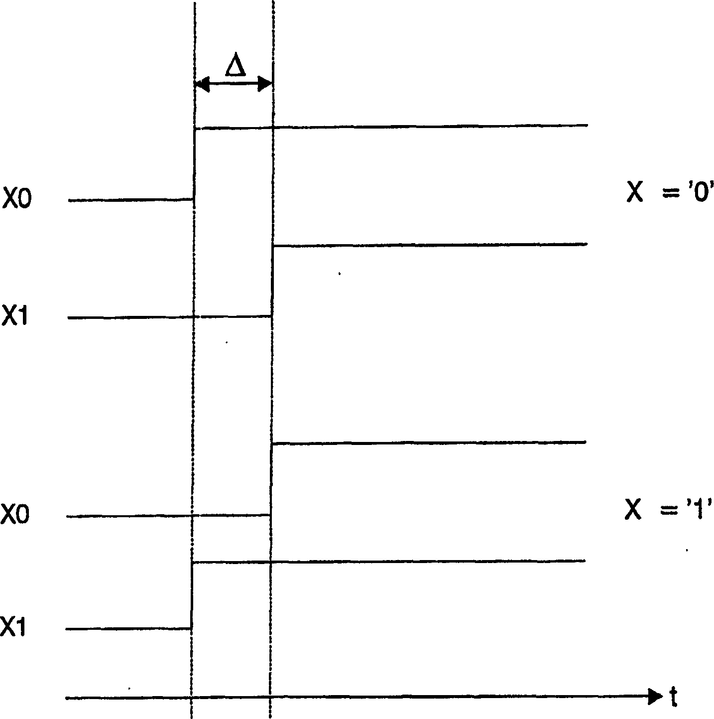
[0023] figure 1 An embodiment of delay coding according to the invention is shown. In delay coding, each binary variable X requires two signal channels X0, X1. The signal channels X0 and X1 are composed of, for example, lead wires, copper wires on a printed circuit board, signal wires in an integrated circuit, and the like. In order for crosstalk to occur, a galvanic coupling between the signal channels X1, X0 must exist, which is usually the case in adjacent signal channels X0, X1. The signal is propagated on two signal paths X0, X1 in the form of a rising or falling transition. The relative delay between the transitions on the two channels X0, X1 when the signal transitions from a first logic level to a second logic level, for example a "0" → "1" transition or a "1" → "0" transition Δ determines the logical value of the output signal X to be generated. If the signal propagating on lane X0 is faster than the signal propagating on lane X1, then X has a logical value "0". ...


PUM


Abstract

The present invention relates to a method for coding information in an electronic circuit and an electronic circuit for coding information, said circuit comprising at least two electrically coupled signal paths (X0, X1). The invention is based on the idea that cross-talk between two electrically coupled signal paths (X0, X1) can be utilized to perform logical computation. A signal is propagating on two signal paths (X0, X1) in the form of either rising or falling transitions. The relative delay between the transitions on the two paths (X0, X1) determines the logic value of the output signal (X) to be produced. If the signal on the first path (X0) propagates faster than the signal on the second path (X1), an output signal (X) having a first logic value is produced. If the signal on the second path (X1) propagates faster than the signal on the first path (X0), an output signal (X) having a second logic value is produced.

Description

technical field [0001] The invention relates to a method of encoding information in an electronic circuit and an electronic circuit encoding information, said circuit comprising at least two electrically coupled signal channels. Background technique [0002] The electronic phenomenon known as crosstalk exists in signal channels that are electrically coupled to each other. Crosstalk manifests itself by inducing voltage glitches on electrically coupled signal paths, which can be viewed as unwanted interference that must be minimized. Crosstalk also manifests itself by changing the speed of the signals traveling on these signal paths. In general, adjacent signal channels affect each other to a greater extent than signal channels separated by a certain distance from each other, because the closer they are to each other, the stronger the electrical coupling will be. [0003] For example, consider that there are two electrically coupled signal channels in an IC. It is often the...

Claims


Application Information

Patent Timeline
Patent Type & Authority Applications(China)
IPC IPC(8): H03K5/06G01R31/3185H01L23/522H03M5/02
CPCG01R31/318538H04L25/0266H01L23/5227H01L2924/0002H01L2924/00H03M5/02
Inventor F·佩斯索拉诺V·E·S·范迪克
Owner III HLDG 6
Why Eureka
Try Eureka