Plug connector having crosstalk compensation

A plug-in connector, connected to technology, applied in the direction of connection, connection of four or more poles, two-part connection device, etc., can solve the problems of complicated connection of flexible printed circuit boards, etc., to achieve simplified assembly, high data transmission. effect of speed

Active Publication Date: 2016-01-13
HARTING ELECTRIC GMBH & CO KG
View PDF8 Cites 5 Cited by
  • Summary
  • Abstract
  • Description
  • Claims
  • Application Information

AI Technical Summary

Problems solved by technology

[0006] The disadvantage of this prior art is that, during the production of the plug-in connector, it is positioned with the required precision in the final position and finally fixed and, if necessary, electrically conductive, for example by welding It is very complicated to connect the flexible printed circuit board to the end of the other free-standing contact

Method used


Image

  • Plug connector having crosstalk compensation
  • Plug connector having crosstalk compensation
  • Plug connector having crosstalk compensation

Examples


Embodiment Construction

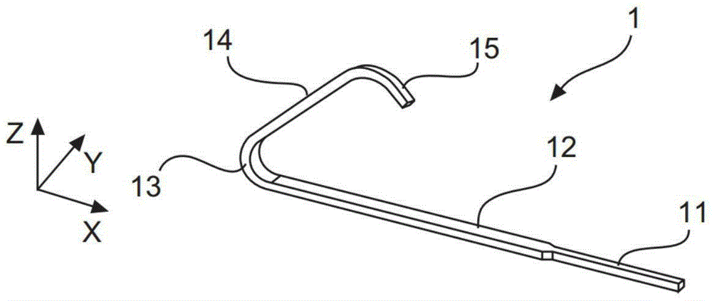
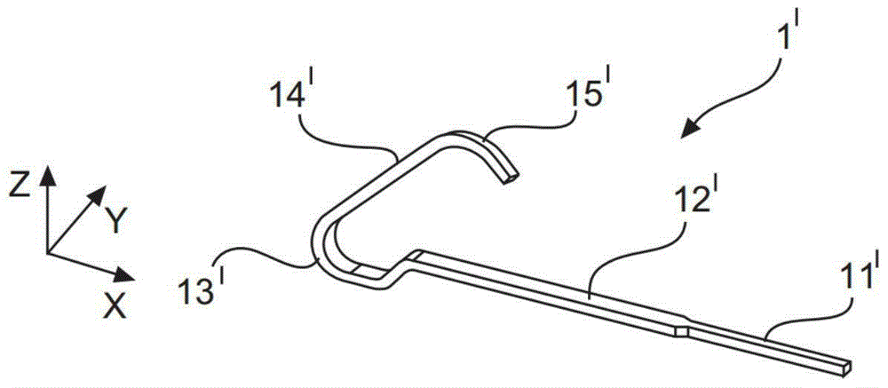
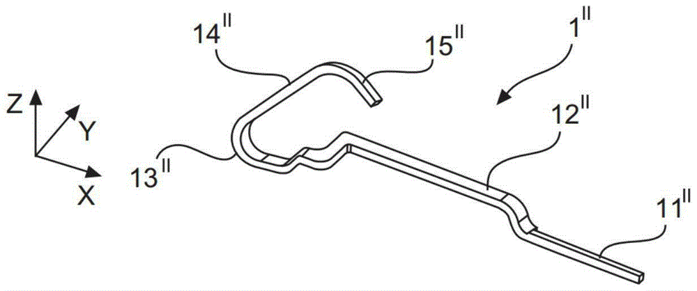
[0041] Figure 1a , 1b , 1c and 1d show the main form of each contact 1, 1', 1", 1"'. All contact pieces 1, 1', 1", 1"' are designed in one piece, made of electrically conductive elastic material, and each contact piece has a connection area 11, 11', 11", 11"', subsequently is the holding area 12, 12', 12", 12"', followed by the bending area 13, 13', 13", 13"', followed by the contact area 14, 14', 14", 14"', followed by the Angled end regions 15, 15', 15", 15"'. The connection area 11, 11', 11", 11"' is bounded by the holding area 12, 12', 12", 12"' since it is narrower.

[0042] Figure 1a A straight contact 1 is shown. Its holding area 12 forms a linear extension of the connection area 11 . The holding area 12 and the connecting area 11 extend in the X direction in a first horizontal plane E1 which is not shown in the figures for the sake of clarity.

[0043] Figure 1b An offset contact 1' is shown. It differs in its main design from a straight contact 1 essentially...


PUM


Abstract

The invention relates to a plug connector that is comparatively simple to produce, e.g. by MID technology, but which nevertheless ensures good crosstalk compensation and hence a high data transfer rate. The contact support thereof consists of two bonded contact support parts. The contacts are arranged between said contact support parts. A separate electrically conductive compensation coating can be provided in each contact support part. Each of the electrically conductive compensation coatings has an attachment surface for establishing an electrically conducting connection to an associated contact. Each of the electrically conductive compensation coatings also has at least one coupling surface which is provided for specific capacitive coupling with one or more further contacts. An insulating foil or a part of an insulating foil that acts as dielectric and spacer is arranged between each coupling surface and the associated contact. Through skilful choice of the contacts to be coupled and the capacitance of the coupling, a good compensation of undesirable crosstalk can thus be achieved in a simple manner.

Description

technical field [0001] The invention relates to a plug-in connector according to the preamble of independent claim 1 . [0002] Such plug-in connectors, such as RJ45 connector jacks, are used for transmitting high-frequency data signals. Background technique [0003] Document DE69927451T2 discloses a modular electrical plug-in connector with reduced crosstalk. This document discloses the use of a printed circuit board which can be equipped with a first conductor and a second conductor. Between the second conductor (for example an insulation displacement terminal provided at the cable termination) and the first conductor (for example a plug-in contact), the printed circuit board has a conductive path on the outer layer. On the inner layer, the printed circuit board has capacitors for capacitively coupling the conductive paths in a targeted manner in order to influence the crosstalk behavior of the plug-in connector in this way. This means that the targeted capacitive coupl...

Claims


Application Information

Patent Timeline
Patent Type & Authority Applications(China)
IPC IPC(8): H01R13/6466H01R24/64H01R13/6467
CPCH01R13/6466H01R13/6467H01R24/64Y10S439/941H01R2107/00H01R13/6464
Inventor M·林德卡普M·舒尔特
Owner HARTING ELECTRIC GMBH & CO KG
Why Eureka
Try Eureka