Electric tool safety special spanner

An electric tool and safe technology, applied in the direction of wrenches, manufacturing tools, screwdrivers, etc., can solve the problems of inability to install or disassemble with screws and nuts, inconvenient to install and disassemble with electric tools, and inconvenient to operate, and achieve novel structure and reliable performance. , the effect of simple appearance

Inactive Publication Date: 2005-10-26
绍兴市上虞东方铜业工贸有限公司
View PDF0 Cites 2 Cited by
  • Summary
  • Abstract
  • Description
  • Claims
  • Application Information

AI Technical Summary

Problems solved by technology

Its shortcomings: first, it is inconvenient to operate, and two wrenches are required to cooperate with each other; second, it is unsafe, when the force is improper or too strong, if the wrench slips off the working force point, it is easy to cause personal injury
Its disadvantages: First, when the device rotates with the shaft, it cannot be used to install or disassemble the screw and nut, so it cannot be used for the installation and disassembly of electric tools

Method used


Image

  • Electric tool safety special spanner
  • Electric tool safety special spanner
  • Electric tool safety special spanner

Examples


Embodiment 1

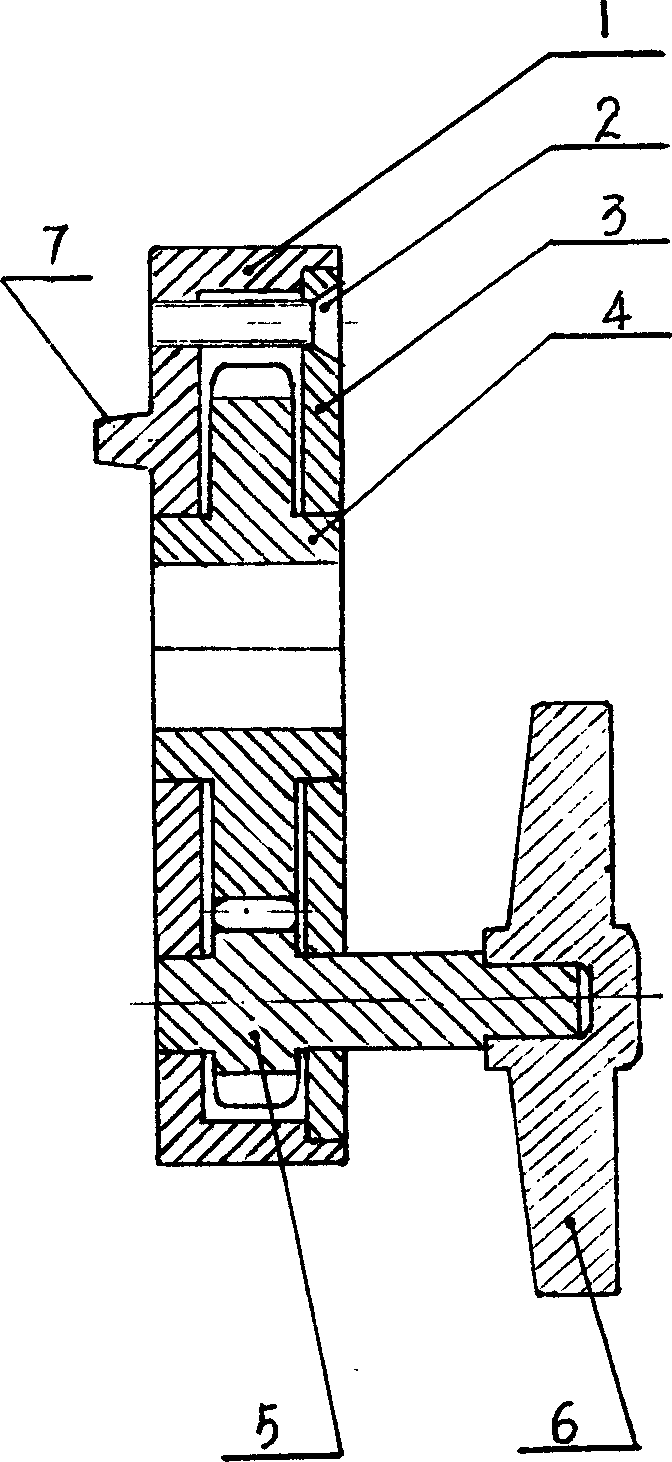
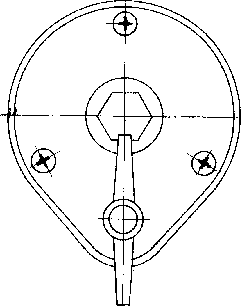
[0011] Embodiment 1: with reference to attached figure 1 and 2 . Special wrench for electric tool safety, the positioning loading and unloading surface of the housing 1 is provided with an eccentricity support point 7 and a wrench head 4 (the 4 here refers to the wrench head in the wrench head gear), which are located in the gear sets 4 and 5 in the housing The power output shaft drives the wrench to rotate, and the gear set constitutes an offset transmission torsion structure, and the power input gear 5 in the gear set is connected with the power input shaft and driven by the power input shaft to rotate. The positioning support point 7 is a boss or a groove and has an integral structure or a split connection structure with the shell 1 surface; the wrench head 4 is a socket wrench head or a convex wrench head, and the socket wrench head and the convex wrench head are internal and external. Multi-deformed inner hexagonal or inner square or inner triangle (see the common hardw...

Embodiment 2

[0012] Embodiment 2: On the basis of Embodiment 1, the end of the wrench head 4 is a through hole, and magnets 16 are placed around the through hole at the end of the wrench head. Figure 4 .

Embodiment 3

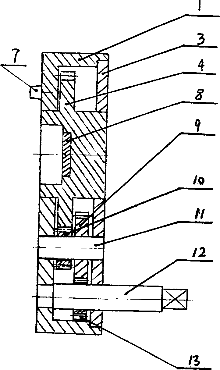
[0013] Embodiment 3: with reference to attached image 3 . On the basis of Embodiment 1, the gear set consists of the wrench head shaft power output gear 4 (also known as the wrench head gear, that is to say, the wrench gear is composed of the wrench head and the gear, and the outer diameter of the wrench head is the gear shaft), The first-stage bridge gear 9 and 10 and shaft power input gear 13 are composed of the input shaft 12 to drive the input gear 13 to rotate, the input gear 13 meshes with the large gear 9 in the bridge gear, the pinion gear 10 in the bridge gear and the wrench head The gear meshes and drives the wrench head gear to rotate, and the bridge gear is composed of the bridge gear 9 and the bridge pinion 10 and under the effect of the shaft 11, the two rotate synchronously. The wrench head gear is formed integral structure by gear and wrench head or is formed integral structure by split, and the technology that forms is prior art, does not narrate at this; Th...


PUM


Abstract

A high-safety special spanner for installing or detaching the saw blade, abrasive disc, or cutting blade in electric tool features that an eccentrical supporting point and spanner head are arranged on the locating-installing-detaching surface of casting, the spanner head is driven by the power output axle in gear cluster, and the power input axle is connected with the power input gear in gear cluster.

Description

Technical field: [0001] The invention relates to the installation and disassembly of a saw blade, a grinding wheel and a resin cutting blade in an electric tool, and belongs to the field of special wrench manufacturing for electric tools. Background technique: [0002] Of the various power tools currently on the market, the installation, disassembly and installation of saw blades, grinding wheels, and resin cutting blades all require two wrenches to complete, and one of the wrenches acts on the shaft of the power tool to make it It cannot be rotated with the direction of rotation of the removal or installation wrench. The two need to act on a large force and in opposite directions to complete the removal or installation of the screw or nut. Its disadvantages: the one, inconvenient operation, need two wrenches to cooperate with each other; the second, it is unsafe, if the wrench slips off the working force point when using improper force or too much force, it will easily caus...

Claims


Application Information

Patent Timeline
Patent Type & Authority Applications(China)
IPC IPC(8): B25B17/02
Inventor 柴小生段媛女相建民
Owner 绍兴市上虞东方铜业工贸有限公司
Why Eureka
Try Eureka