Blowout prevented fire hydrant, and fire fighting terminal providing flux information

A fire hydrant and anti-surge technology, applied in the field of fire hydrant flow measurement device, fire hydrant anti-surge valve, anti-surge fire hydrant and flow information fire terminal field, can solve the problem of no detection device or communication device, no water flow for fire hydrant, no water source waste, etc.

Inactive Publication Date: 2005-10-26
郭建国 +1
View PDF1 Cites 8 Cited by
  • Summary
  • Abstract
  • Description
  • Claims
  • Application Information

AI Technical Summary

Problems solved by technology

The fire hydrant was broken and the "spring" water gushed out, which not only damaged the fire-fighting facilities; it also caused a lot of waste of water sources, traffic blockage, and property losses caused by flooding of nearby shops and residents
The transition from the planned economy to a commodity economy has also brought new problems to the management of fire hydrants: traditional fire hydrants have no water flow metering devices, and there are no detection devices or communication devices for their various states. Turned into a commodity, the water intake and water consumption

Method used


Image

  • Blowout prevented fire hydrant, and fire fighting terminal providing flux information
  • Blowout prevented fire hydrant, and fire fighting terminal providing flux information
  • Blowout prevented fire hydrant, and fire fighting terminal providing flux information

Examples


Embodiment 1

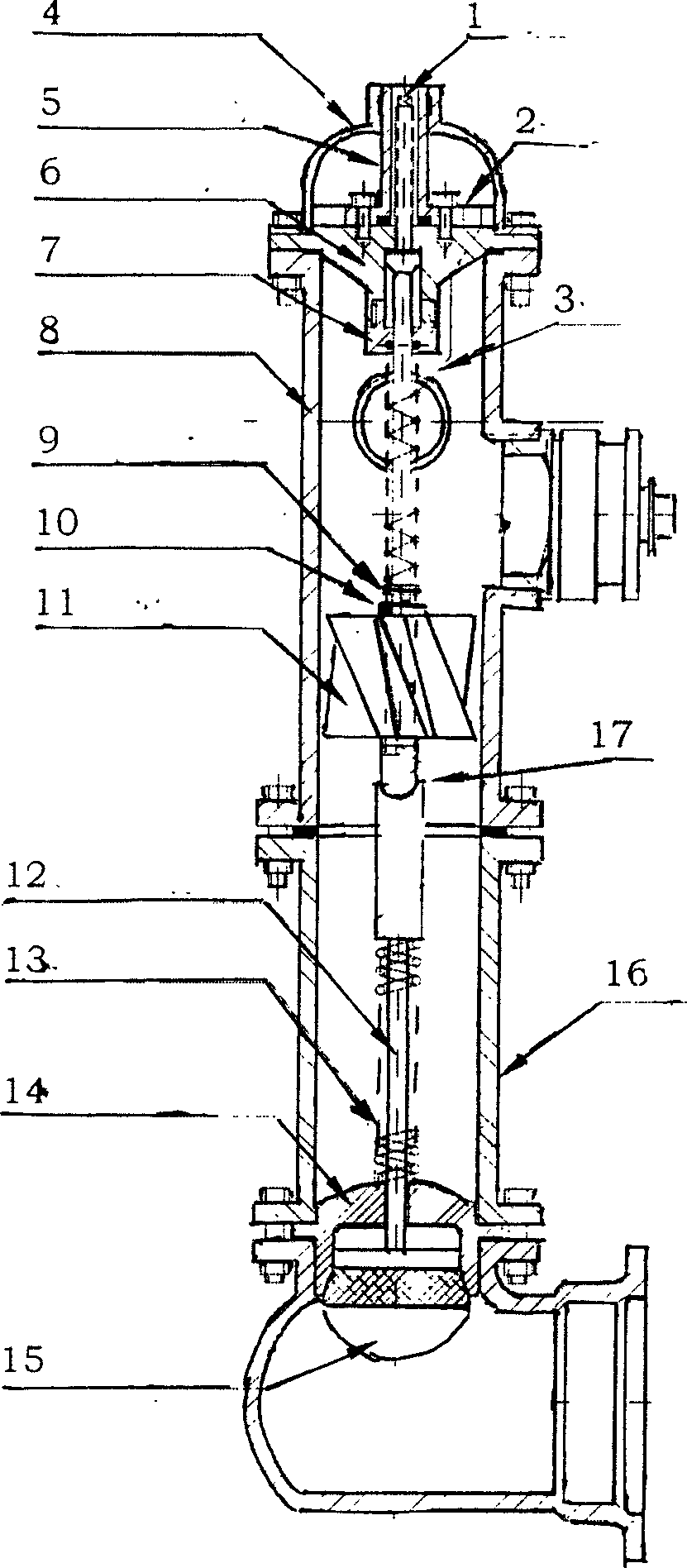
[0026] Embodiment 1, with reference to Fig. 1~ figure 2 :

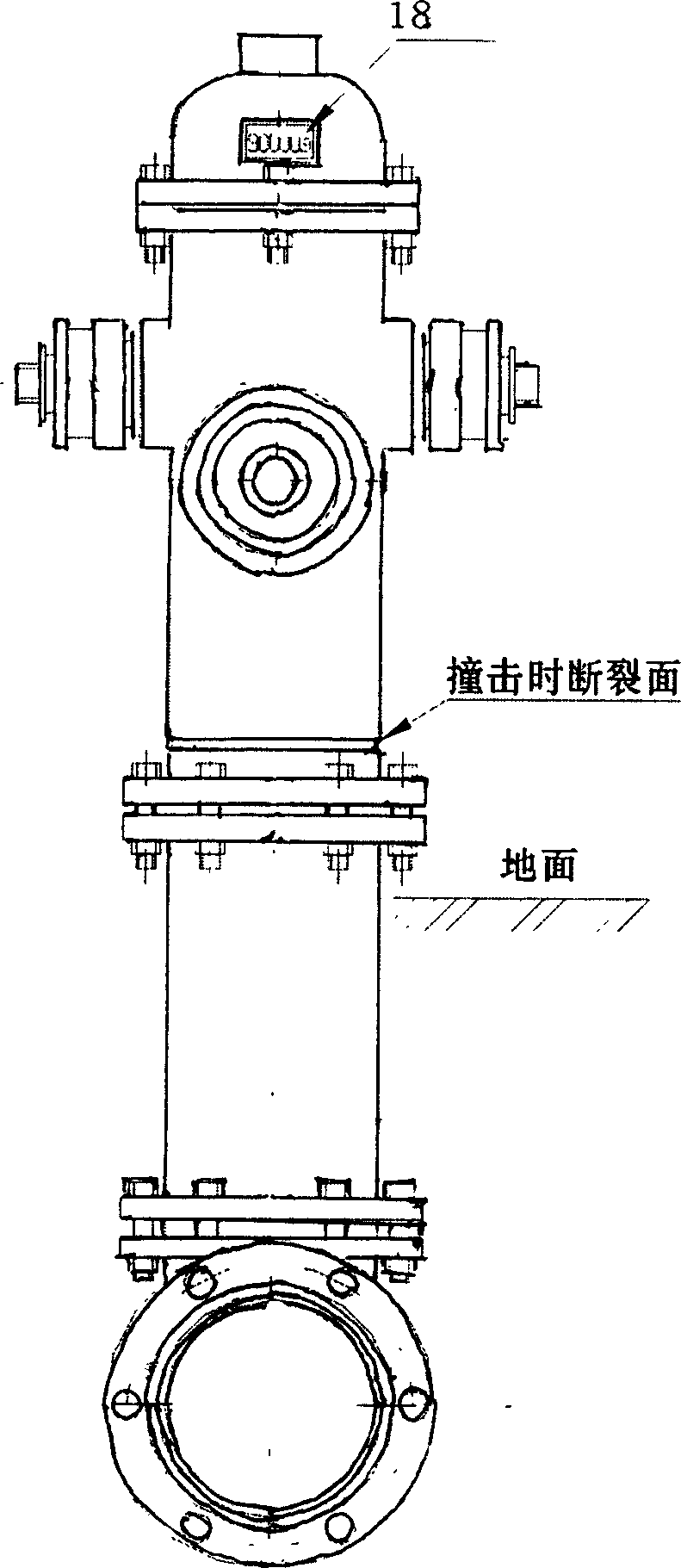
[0027] The anti-splash fire hydrant has an upper body 8 and a lower body 16. The upper and lower bodies are connected by bolts or screws. parts. The upper bolt body 8 is provided with a valve bolt and a valve bolt rod 1, and the lower end of the valve bolt rod is connected with an anti-surge valve: the anti-surge valve is composed of a leaky valve seat 14 and a conical valve disc 15, and the conical valve disc 15 is connected There is a disc rod 12 on which a spring 13 is arranged; the disc rod and the valve bolt rod are connected through a hemispherical joint 17 . The hemispherical joint 17 connecting the valve screw rod and the disc rod is arranged at the connection plane of the upper and lower bolt bodies, that is, the hemispherical joint is arranged at the position where the fire hydrant is flush with the ground plane or slightly higher than the plane. A metering impeller 11 is installed on the disc rod, the m...

Embodiment 2

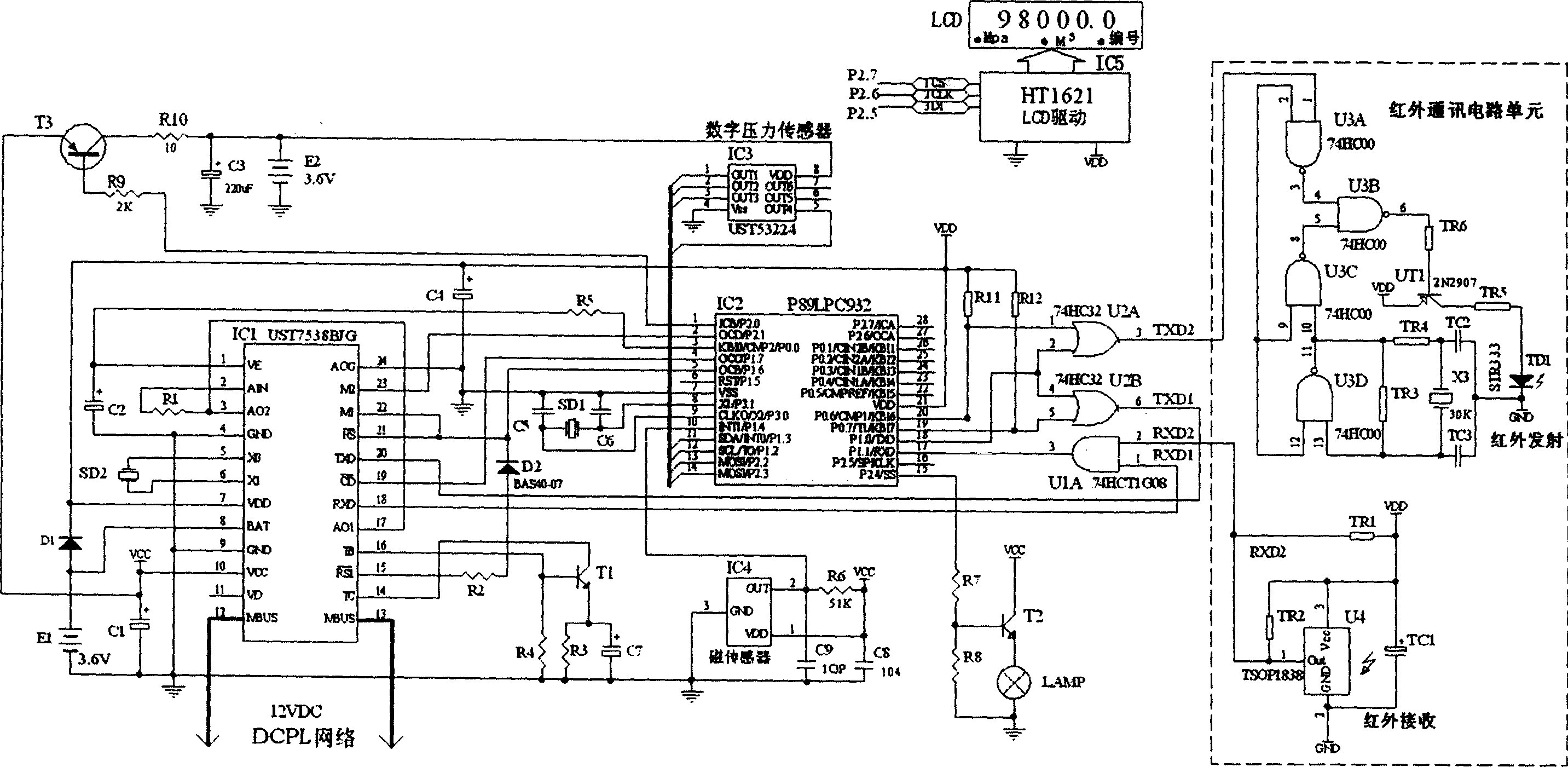
[0034] Embodiment 2 is basically the same as Embodiment 1, but a valve state sensor and a water pressure sensor are provided on the waterway of the fire hydrant, and a microprocessor is provided at the same time; the microprocessor is connected with a DCPL network communication interface circuit, and the flow rate Data acquisition circuit, valve state acquisition circuit, and water pressure detection data acquisition circuit, among which the flow data acquisition circuit, valve state acquisition circuit, and water pressure detection data acquisition circuit are respectively connected with the flow metering device, valve state sensor and water pressure in the fire hydrant. It is connected to the pressure sensor and connected to the network through the communication interface to form a fire hydrant terminal device for flow measurement information. All anti-splash fire hydrants and flow metering information fire hydrant terminal devices are connected to the network for easy monito...


PUM


Abstract

The spewing-preventing fire hydrant equips valve bolt and valve bolt rod. The lower part of the valve bolt rod links valve. Its characteristic is that the valve is spewing-preventing valve, comprising of hollowing-out valve seat and conic valve clack. On the valve clack there links valve clack rod on which equips spring. The valve clack rod is connected to the valve bolt through hemispherical joint. When the fire hydrant is impacted, the spigot body is separated at the surface of fracture. Because the hemispherical joints of the valve bolt rod and clack rod pole are separated, it can protect the underground spigot body. The often closed unidirectional valve is operated by any outer force, and the subulate valve petal and hollowing-out valve pedestal are operated by the spring force, they all form closed states, and can effectively prevent spewing. The optimized plan equips current capacity measurement device: on the valve clack rod there is measuring impeller on which fixed small magnet, and the corresponding place of the spigot body fixes magnetism sensor whose output is connected to the microprocessor. In the waterway there can be also equipped with valve state sensor, hydraulic pressure sensor and network communication interface, to structure fire hydrant current capacity measurement information terminal device and form network.

Description

technical field [0001] The present invention relates to a fire-fighting equipment, in particular to an anti-surge fire hydrant and a flow information fire-fighting terminal, including a fire hydrant anti-surge valve, a fire hydrant flow metering device, and an information fire hydrant terminal. : Information fire hydrant terminal. Background technique [0002] The fire hydrant is one of the indispensable infrastructures in modern cities. Its structure is: a valve bolt is arranged on the top of the hydrant body, and the water pipe valve located at the bottom of the hydrant body is connected through the valve bolt rod. The functions and appearance of fire hydrants have basically remained unchanged for decades, and it has been revealed in many aspects that they cannot meet the needs of modern urban construction. For example, with the rapid increase of urban motor vehicles and the unevenness of drivers' driving skills, incidents of fire hydrants being damaged by vehicles in var...

Claims


Application Information

Patent Timeline
IPC IPC(8): E03B9/02
Inventor 郭建国黄安宁
Owner 郭建国
Why Eureka
Try Eureka