Electronic display and control device for a measuring instrument

A measuring instrument and electronic display technology, applied in the field of measuring systems for geodetic surveying

Inactive Publication Date: 2005-10-26
LEICA GEOSYSTEMS AG
View PDF6 Cites 43 Cited by
  • Summary
  • Abstract
  • Description
  • Claims
  • Application Information

AI Technical Summary

Problems solved by technology

In this case, if a target is actively irradiated by the emitted radiation and is detected or tracked on the basis of the reflected radiation, then in the case of devices of the pr...

Method used


Image

  • Electronic display and control device for a measuring instrument
  • Electronic display and control device for a measuring instrument
  • Electronic display and control device for a measuring instrument

Examples


Embodiment Construction

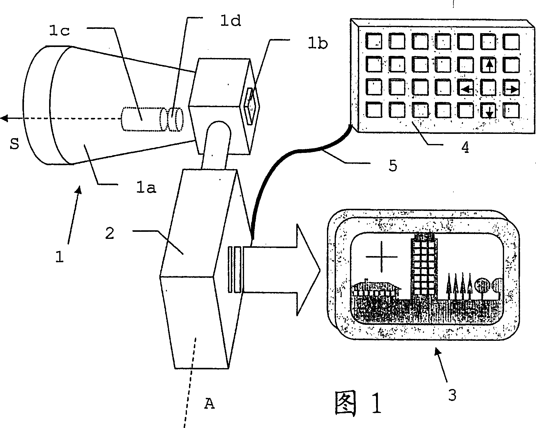
[0045] Figure 1 shows a block diagram of an electronic display and control device according to the invention, which can be used for the alignment and measurement data capture of different types of measuring instruments. In this case, the objective part 1a together with the electron capture device 1b forms the capture device 1 required for the measurement process. The direct viewing device for the naked eye is replaced by a suitable device for image capture, such as a video camera or a CCD camera. In addition to structural advantages, the electronic device can also realize selective or extended use of spectral ranges that cannot be directly touched by the naked eye. In the embodiment illustrated here, the radiation source 1c and the alignment device 1d are additionally integrated in the capture device 1, so that parts of the capture device 1 are available not only for the beam path of the capture device 1b, but also for the radiation source 1c's ray path utilization.

[0046]...


PUM


Abstract

The invention relates to an electronic display and control device for a geodesic measuring device (12) containing capturing means (1') and representation means for detecting and reproducing a measuring range (11) together with input means for controlling the measuring processes. The radiation beam (S) necessary for said measuring processes is emitted by a radiation source and is influenced in the direction of emission thereof by orientating means such that it can be orientated onto a selected target within the measuring range (11) without the capturing means being displaced. Determining the target and initiating the measuring process occurs by displacing a position mark (3a) on a screen. A suitable operating module can be produced by suitably combining the representation means with means for inputting data. Said module can also be used independently from and separately from a measuring device (12,12') which is connected thereto by communication means. The use of said module together with a plurality of measuring devices as sensor components, enables the formation of remote-controlled geodesic measuring systems.

Description

technical field [0001] The invention relates to an electronic display and control device according to the preamble of claim 1 as well as a geodetic measuring instrument according to claim 15 , a module part according to claim 23 and a geodetic survey according to claim 24 Use the measurement system. Background technique [0002] In order to capture properties of predetermined points in the measurement environment, especially data having a spatial relationship, many measurement devices are known in the past. In this case, the position of the measuring device, including possibly existing reference points, and the azimuth, distance and angle to the measuring point are listed as spatial reference data. Much of the past improvements involved the use of new technical methods with increased precision and speed. [0003] A well-known example of such a measuring device is the theodolite. An overview of prior art geodetic measuring devices is provided by: "Elektronische Entfernungs...

Claims


Application Information

Patent Timeline
IPC IPC(8): G01C1/04G01C15/00G01S7/00G01S7/481G01S7/497G01S7/51
CPCG01S7/51G01S7/4812G01S7/497G01C15/002G01S7/4817G06F3/0488G01S7/003G01C1/04
Inventor 格哈德·克恩克劳斯·施奈德派厄斯·福尔伯格于尔格·欣德林
Owner LEICA GEOSYSTEMS AG
Why Eureka
Try Eureka