Optical disk apparatus

An optical disc device and optical disc technology, which are applied to beam guiding devices, optical recording heads, recording/reproducing by optical methods, etc., can solve the problems of inability to read signals, incapable of receiving signal light, incapable of collecting and tracking, etc. Achieve the effect of eliminating misreading and loss of control

Inactive Publication Date: 2005-11-02
PANASONIC CORP
View PDF1 Cites 0 Cited by
  • Summary
  • Abstract
  • Description
  • Claims
  • Application Information

AI Technical Summary

Problems solved by technology

Therefore, the photodetector 9 cannot receive the signal light reflected from the signal surface 6a, and not only cannot read the signal, but also cannot perform control such as focusing and tracking.

Method used


Image

  • Optical disk apparatus
  • Optical disk apparatus
  • Optical disk apparatus

Examples


Embodiment 1

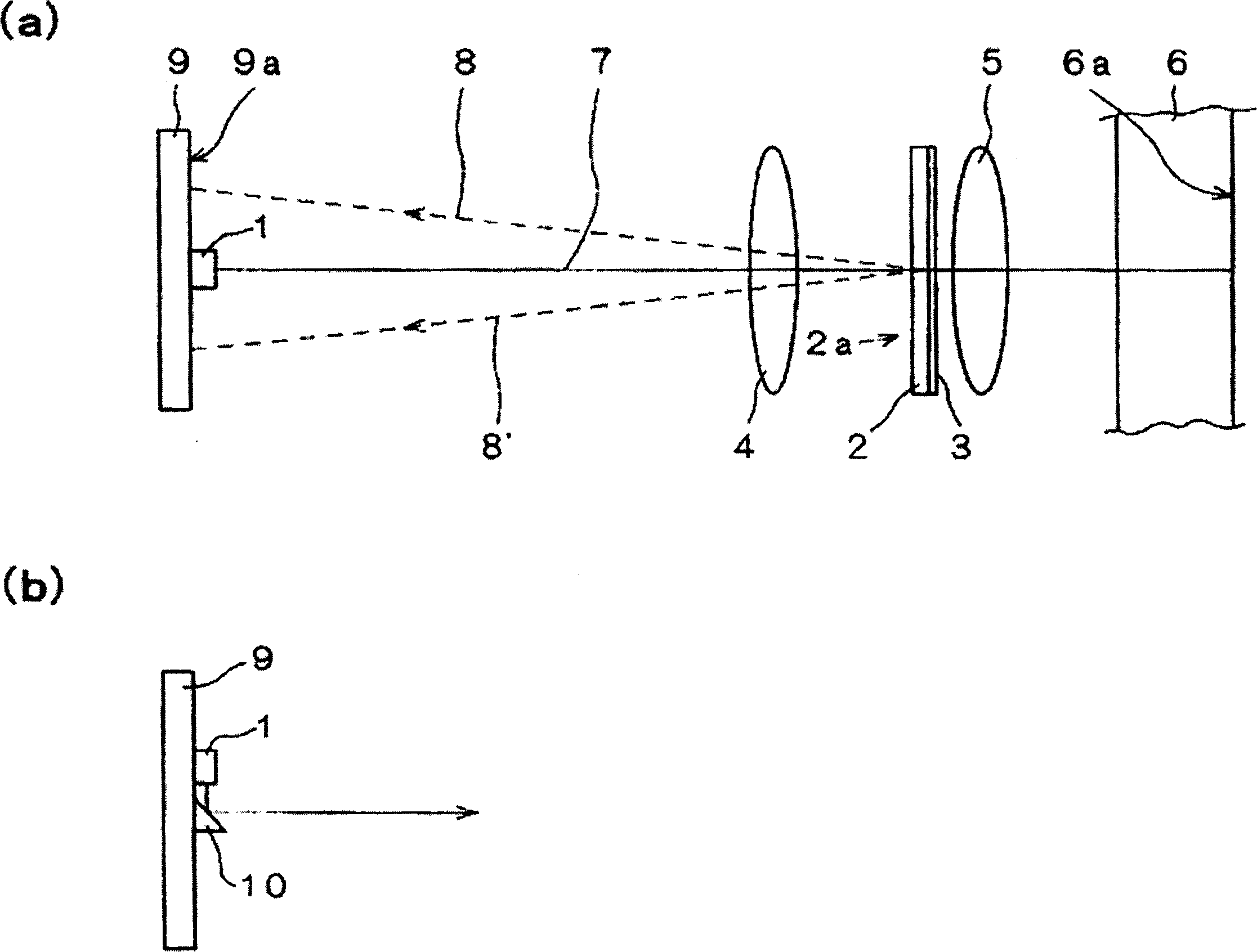
[0072] refer to Figure 1 ~ Figure 4 A first embodiment of the optical disc device of this embodiment will be described.

[0073] First, refer to figure 1 (a). figure 1 (a) shows the configuration of main parts of the optical pickup of the optical disc device of this embodiment. figure 1 (b) shows the light source 1 and the sides related to its periphery.

[0074] The optical pickup of this embodiment, such as figure 1 As shown in (a), it includes a photodetection substrate 9 on which a light source 1 such as a semiconductor laser is mounted, and an optical system. The optical system has a collimator lens 4 arranged on an optical axis 7 , a polarization hologram substrate 2 , a distributed wavelength plate 3 and an objective lens 5 . The distributed wavelength plate 3 is formed on the same substrate as the hologram surface 2 a of the polarization hologram substrate 2 , and moves integrally with the objective lens 5 . One of the most characteristic components in this ...

Embodiment 2

[0123] Next, refer to Figure 5 ~ Fig. 7 illustrates the second embodiment of the optical disc device of the present invention.

[0124] In this embodiment, the number of light emitting points of the light source 1 is increased to two. In addition, the pattern of the polarization hologram surface 2a, the detection pattern on the photodetector surface 9a, and the light distribution thereon are different from those of the first embodiment. Except for these points, the optical disc device of this embodiment has the same structure as the optical disc device of Embodiment 1. Therefore, the same parts as those in the description of Embodiment 1 are omitted. In addition, the same reference numerals are assigned to the same components as those of the optical disc device according to the first embodiment.

[0125] The light source 1 may mount two semiconductor laser chips of different types, or may be a single semiconductor laser chip that emits laser light of different wavelengths....

Embodiment 3

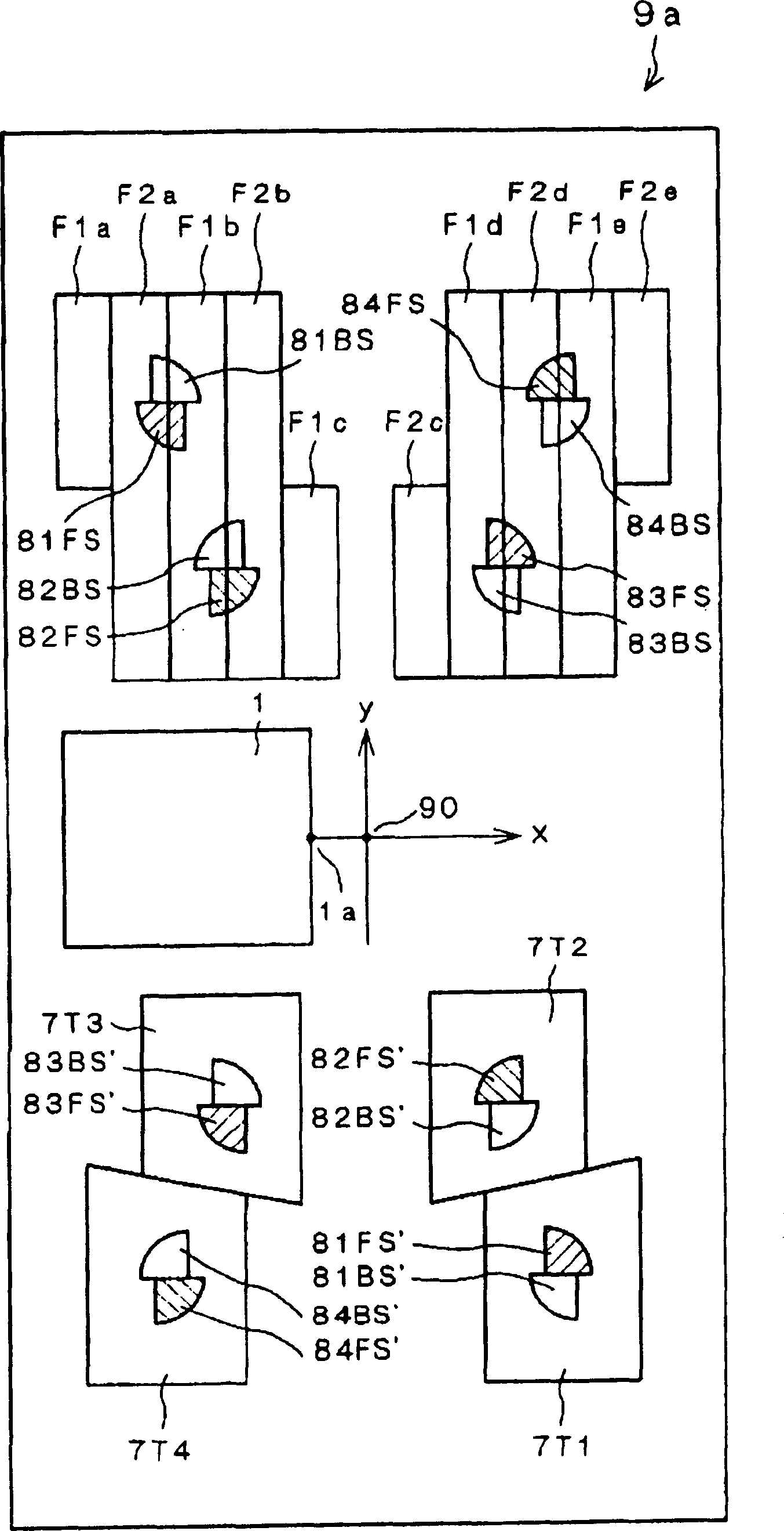
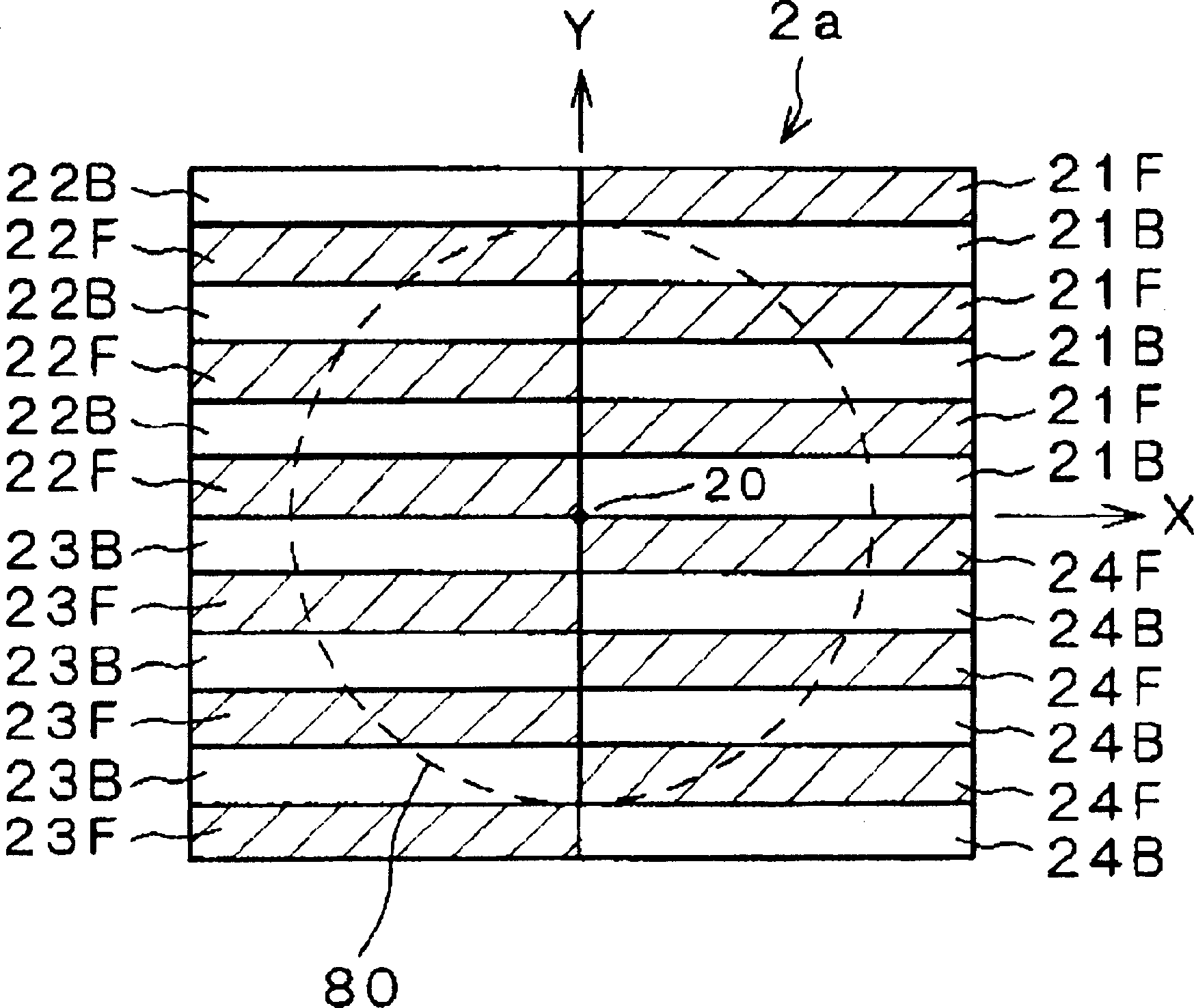
[0151] Next, refer to Figure 8 ~ Fig. 9, illustrate the third embodiment of the optical disc device of the present invention. The optical disc device of this embodiment has the same structure as the optical disc device of the second embodiment except that the pattern of the polarization hologram surface 2a, the detection pattern on the photodetector surface 9a, and the light distribution thereon are different. Therefore, the description of the parts that are the same will be omitted.

[0152] Figure 8 Showing the configuration of the holographic surface 2a of the polarization holographic substrate 2 of this embodiment, Figure 9A , Figure 9B The photodetection surface 9a of this embodiment is shown. Both are top views of the holographic surface 2 a and the light detection surface 9 a viewed from one side of the optical disc substrate 6 . Figure 9A Represents the light spot formed by the return light of the first laser light emitted from the first light-emitting point ...


PUM

PropertyMeasurementUnit
wavelengthaaaaaaaaaa

Abstract

It is intended to provide an optical disk apparatus which detects a light amount greater than zero even when used in conjunction with an optical disk substrate having a large birefringence, so that it is possible to properly read a signal without errors and properly perform optical disk controls. The optical disk apparatus includes: a light source for emitting light; an objective lens for converging the light onto a signal surface of an optical disk; a polarized beam diffraction element for diffracting the light reflected from the optical disk; a photodetector for detecting the light diffracted from the polarized beam diffraction element; and a wavelength plate disposed between the optical disk and the polarized beam diffraction element. The wavelength plate has a two-dimensional array of a plurality of birefringent regions including first and second regions, the first and second regions differing in birefringent phase difference and/or optic axes from each other, and the plurality of birefringent regions including the first and second regions cause the light to have different polarization states.

Description

technical field [0001] The present invention relates to an optical disc device capable of writing data to and / or reading data from an optical disc. In addition, the present invention relates to an optical element that can be preferably applied to such an optical disc device and a method for manufacturing the same. Background technique [0002] The optical disc device includes a motor for rotating the optical disc, an optical pickup (pick-up) for irradiating the optical disc with a light beam, and a signal processing unit for processing recording / reproducing data. Among them, the optical pickup is one of the most important parts for increasing storage density. It is equipped with a light source for generating a light beam, a lens for converging the light beam on the recording surface of the optical disc, and detecting light reflected by the optical disc (reproduction light or signal light). A photodetector that converts an electrical signal. [0003] A known optical disc dr...

Claims


Application Information

Patent Timeline
Patent Type & Authority Applications(China)
IPC IPC(8): G11B7/1353G11B7/1365G11B7/1381
Inventor 西胁青儿百尾和雄麻田润一大谷健二神田裕介
Owner PANASONIC CORP
Why Eureka
Try Eureka