Imaging sensor mounting method and adhesive tape used thereby
A technology of image sensor and installation method, which is applied in the direction of film/sheet-shaped adhesives, adhesives, radiation control devices, etc., can solve the problems of electronic device damage, electronic device resistance reduction, etc., to reduce adhesion, prevent damage, and improve The effect of effective utilization
- Summary
- Abstract
- Description
- Claims
- Application Information
AI Technical Summary
Problems solved by technology
Method used
Image

Examples
Embodiment 1
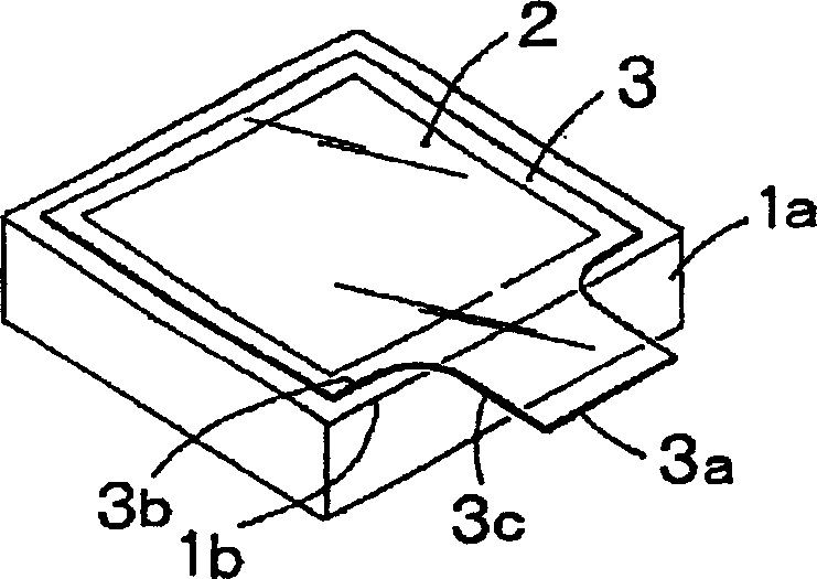
[0088] In polyimide film (Toray Teyubon Co., Ltd. Ripton 100H: thickness 25μm, thermal conductivity at 170°C is 4.1×10 -4 cal / cm·sec·°C) is coated with a silicone adhesive (SD-4580 manufactured by Toray Dou Corning Co., Ltd.) to a thickness of 10 μm to form an adhesive tape, and attached to the surface glass of the CCD package . It was put into a reflow soldering furnace with a maximum temperature of 180°C x 5 seconds (about 90 seconds for a reflow furnace including waste heat, etc.), and mounted on a substrate. Among them, peel off the adhesive tape after the installation is finished.
[0089] As a result, damage or foreign matter was not confirmed on the surface after the stripping of the tape, and normal operation as a CCD was confirmed.
Embodiment 2
[0091] A quaternary ammonium salt (NR-121X manufactured by Colcoat Co., Ltd.) was applied to the back of the substrate of the adhesive tape on a substrate made of polyimide (Capton 100H manufactured by Toray Teubon Co., Ltd.) with a thickness of 25 μm. side. Subsequently, an acrylic adhesive solution was applied on the other side, and dried to obtain an adhesive tape in which an adhesive layer having a thickness of 10 μm was formed.
[0092] After heating this adhesive tape at 180° C. for about 1 hour, the adhesive force was measured in accordance with JIS Z0237, and it was 2.5 N / 19 mm, and the heat shrinkage rate was 0.1%. In addition, peeling of the adhesive tape was not observed, and the maximum value of the discharge capacity was 50 mV.
Embodiment 3
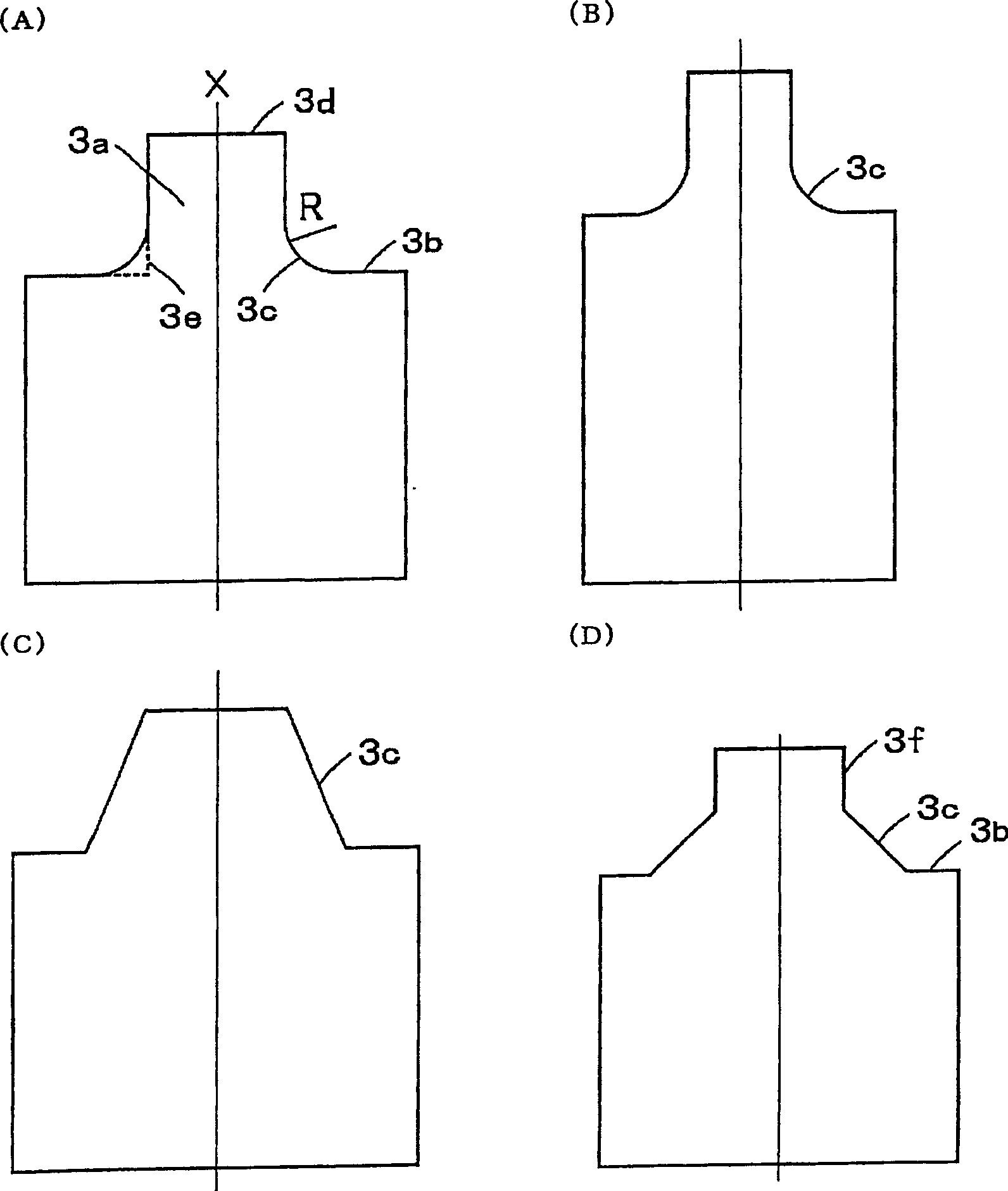
[0094] as above figure 2 As shown in (A), except that the adhesive tape is made into a tape shape with a protruding portion with a protruding length of 4 mm from the 11 mm × 12 mm square covering part through the arc-shaped side part of R = 2 (mm) , An adhesive tape was produced in the same manner as in Example 1. This adhesive tape was bonded to the surface glass of the CCD package, it was put into the reflow soldering furnace of 180 degreeC similarly to Example 1, and it mounted on the board|substrate.
[0095] Then, the adhesive tape can be peeled off from the protruding part without breaking the adhesive tape from the protruding part. No damage or adhesion of foreign matter was found on the surface after the tape was peeled off, and normal operation as a CCD was confirmed.
PUM
| Property | Measurement | Unit |
|---|---|---|
| thickness | aaaaa | aaaaa |
| thickness | aaaaa | aaaaa |
| transmittivity | aaaaa | aaaaa |
Abstract
Description
Claims
Application Information
 - R&D
- Intellectual Property
- Life Sciences
- Materials
- Tech Scout
- Unparalleled Data Quality
- Higher Quality Content
- 60% Fewer Hallucinations
Browse by: Latest US Patents, China's latest patents, Technical Efficacy Thesaurus, Application Domain, Technology Topic, Popular Technical Reports.
© 2025 PatSnap. All rights reserved.Legal|Privacy policy|Modern Slavery Act Transparency Statement|Sitemap|About US| Contact US: help@patsnap.com