Double face scanner

A double-sided scanning and scanner technology, applied in the field of scanners, can solve problems such as out-of-step, vibration and noise, motor deadlock, etc.

Active Publication Date: 2005-11-02
AVISION PRECISION IND (SUZHOU) CO LTD
View PDF0 Cites 5 Cited by
  • Summary
  • Abstract
  • Description
  • Claims
  • Application Information

AI Technical Summary

Problems solved by technology

It is designed with a power source that can output feedback signals, which can solve the problems of out-of-step, motor deadlock, high operating temperature, vibration and noise encountered in the operation of stepping motors in the traditional open-loop control mode. Requirements for scanners with high speed, high load, large load variation, less vibration and low noise

Method used


Image

  • Double face scanner
  • Double face scanner
  • Double face scanner

Examples


Embodiment 1

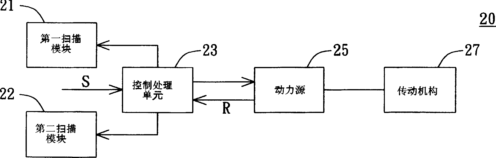
[0019] Please refer to Figure 2A , which shows a block diagram of a duplex scanner according to Embodiment 1 of the present invention. exist Figure 2A Among them, the duplex scanner 20 at least includes a first scanning module 21 , a second scanning module 22 , a control processing unit 23 , a power source 25 and a transmission mechanism 27 . The first scanning module 21 is used for scanning a document to be scanned (not shown in Figure 2A middle) and capture an image of the front side of the document to be scanned. The second scanning module 22 is used to scan the back of a document to be scanned, and capture an image of the back of the document to be scanned. The transmission mechanism 27 is used to generate a relative movement between the document to be scanned and the first scanning module 21 and the second scanning module 22 .

[0020] Such as Figure 2B As shown, assuming that the first scanning module 21 and the second scanning module 22 are stationary, then F...

Embodiment 2

[0024] Please refer to Figure 3A , which shows a block diagram of a duplex scanner according to Embodiment 2 of the present invention. In figure 3A, the duplex scanner 40 at least includes a first scanning module 41, a second scanning module 44, a control processing unit 43, a first power source 45, a second power source 46, a first transmission mechanism 47 and a second Transmission mechanism 48. The first scanning module 41 is used for scanning a document to be scanned (not shown in Figure 3A middle) and capture an image of the front side of the document to be scanned. The second scanning module 44 is used to scan the back of a document to be scanned, and capture an image of the back of the document to be scanned. The first transmission mechanism 47 is used to move the first scanning module 41, and the second transmission mechanism 48 is used to move the document to be scanned.

[0025] Such as Figure 3B As shown, the double-sided scanner 40 can be a flat-bed type do...

Embodiment 3

[0029] Please refer to Figure 4 , which shows a block diagram of a duplex scanner according to Embodiment 3 of the present invention. The difference between the double-sided scanner 50 of the present embodiment and the double-sided scanner 40 of the second embodiment lies in the first control processing unit 53 and the second control processing unit 54, and the same reference numerals continue to be used for other identical components. And will not repeat them here. exist Figure 4 Among them, both the first control processing unit 53 and the second control processing unit 54 can receive the scanning instruction S, or the first control processing unit 53 or the second control processing unit 54 receives the scanning instruction S. The first control processing unit 53 receives the scanning instruction S, and determines whether the first scanning module 42 has reached the positioning. If the first scanning module 41 has not reached the position, the first control processing ...


PUM


Abstract

A double-faced scanner comprises first and second scan module, drive mechanism, power source and control process unit. The first scan module scan the front face of document waiting for scanning and acquire front face image of the document; second scan module scan the back face of document waiting for scanning and acquire back face image of the document. Drive mechanism drives document waiting for scanning, first and second scan module to move relatively. Power source bring along drive mechanism and output at least one feedback signal. Control unit receives a scan command and control the drive of power source to drive mechanism by the command. Control unit receives feedback signal and control first and second scan module to scan with double faces by the signal.

Description

technical field [0001] The present invention relates to a scanner, in particular to a duplex scanner. Background technique [0002] With the advancement and development of science and technology, the integration and application of multi-media has become a trend. The so-called multimedia refers to data content including various data forms such as text, video, and sound. In order to display data in the form of multimedia, a variety of multimedia devices that can capture images or sounds have been developed. For image processing, scanners are one of the image capture tools that users often use. one. [0003] Please refer to Figure 1A , which shows a block diagram of a conventional sheet-feed type single-sided scanner with a step motor. exist Figure 1A Among them, the scanner 10 includes an automatic document feeder (ADF) charge coupled device (CCD) 11 , a controller 12 , a stepping motor 13 and a roller set 14 . When the scanner 10 starts to...

Claims


Application Information

Patent Timeline
Patent Type & Authority Applications(China)
IPC IPC(8): H04N1/203
Inventor 陈琰成陈星嘉
Owner AVISION PRECISION IND (SUZHOU) CO LTD
Why Eureka
Try Eureka