
Method for forming pattern using printing method

A pattern and printing plate technology, applied in the field of pattern formation using printing method, can solve problems such as reducing productivity

Inactive Publication Date: 2005-11-09
LG DISPLAY CO LTD
View PDF0 Cites 10 Cited by
  • Summary
  • Abstract
  • Description
  • Claims
  • Application Information

AI Technical Summary

Problems solved by technology

[0008] In addition, in order to form the pattern of the liquid crystal display device, this photolithography process must be repeated several times, thus lowering the productivity

Method used


Image

  • Method for forming pattern using printing method
  • Method for forming pattern using printing method
  • Method for forming pattern using printing method

Examples


Embodiment Construction

[0022] Hereinafter, embodiments of the present invention will be described in detail, examples of which are illustrated in the accompanying drawings.

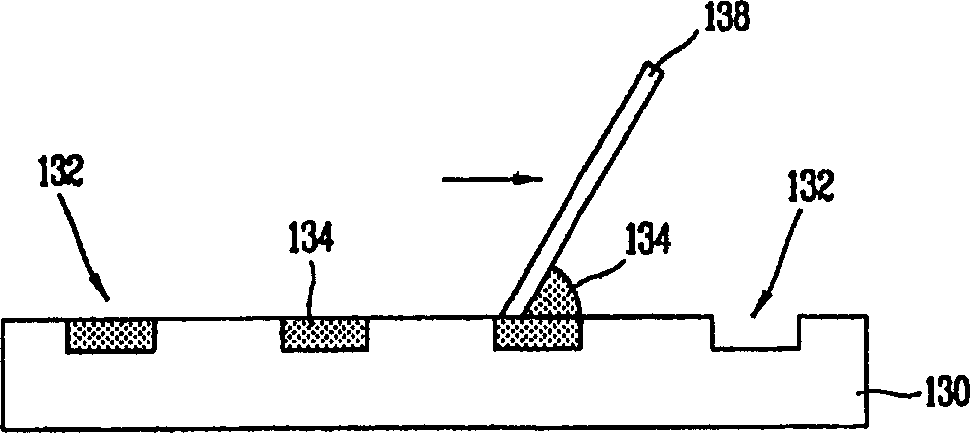
[0023] The present invention provides a printing method for forming active device patterns of a display device such as a liquid crystal display device. Specifically, the present invention provides a gravure offset printing method in which ink is arranged on a gravure plate, excess ink is removed by scraping, and then printing is performed.

[0024] In gravure offset printing, since the ink is transferred to the substrate using a transfer roller, it is possible to form a pattern with a single transfer even in a display device with a large display area, because the used The transfer roller corresponds to the area required for the display device. Gravure offset printing can be used to form various patterns used in display devices (such as gate lines and data lines connected to TFTs, pixel electrodes, metal patterns used in capaci...


PUM


Abstract

A method for forming a pattern is provided that includes: providing a cliche having a plurality of convex patterns; applying an adhesive force reinforcing agent onto each surface of the convex patterns; forming an etching object layer on a substrate and then applying ink onto an upper portion of the etching object layer; attaching the cliche and the substrate to each other such that the convex patterns onto which the adhesive force reinforcing agent is applied can come in contact with the ink applied onto the etching object layer; and forming ink patterns which selectively remain on the etching object layer by separating the substrate from each other.

Description

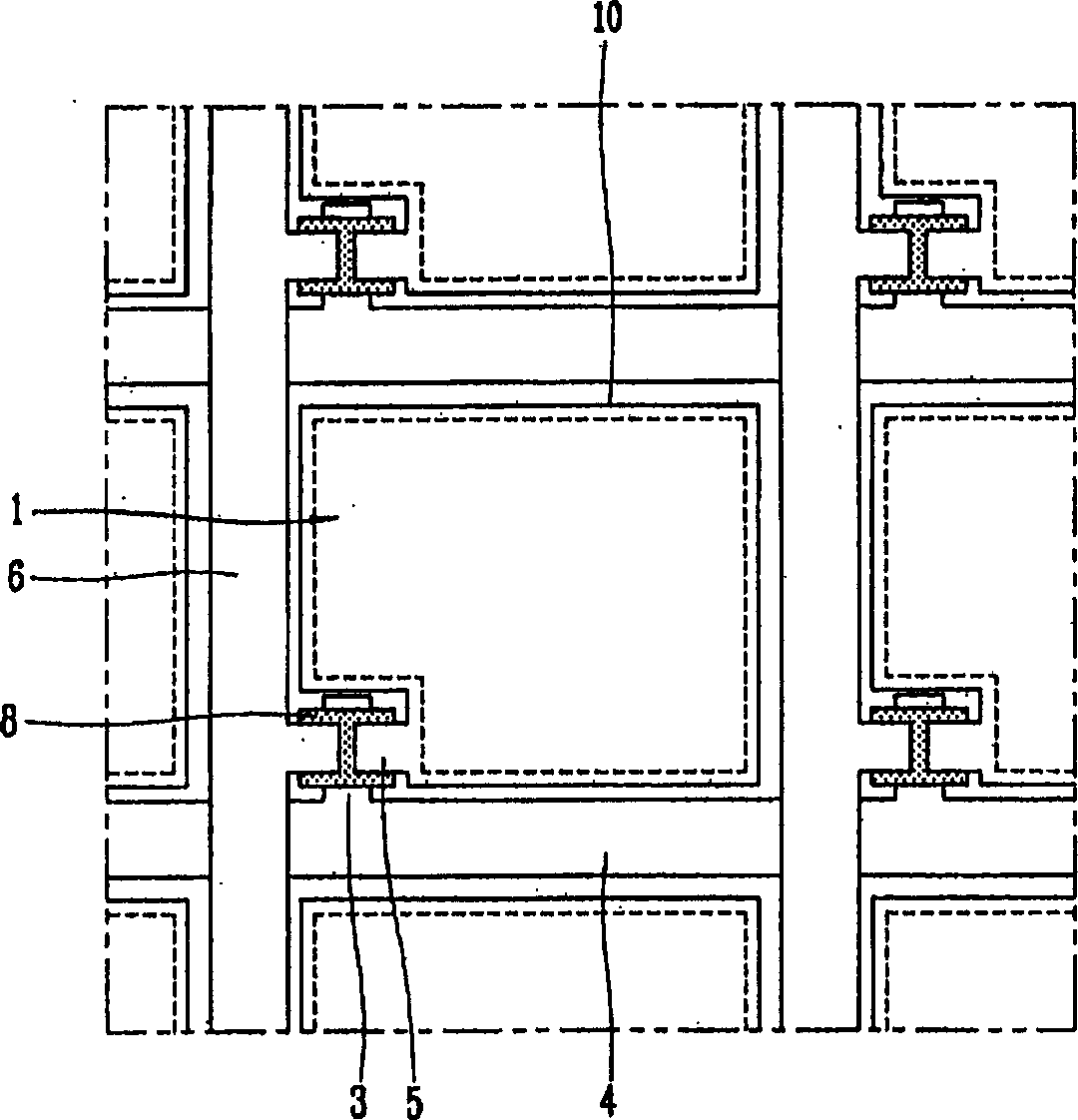
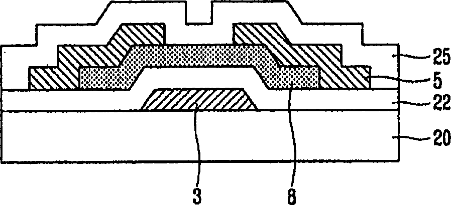
technical field [0001] The present invention relates to a printing method for forming a pattern in a liquid crystal display panel, and more particularly, to a method for forming a pattern with a uniform thickness on a substrate. Background technique [0002] Display devices, particularly flat panel displays such as liquid crystal display (LCD) devices, are driven by active devices such as thin film transistors disposed at individual pixels. This driving method is called an active matrix driving method. According to the active matrix driving method, active devices are arranged at each pixel to drive the corresponding pixel. [0003] figure 1 An active matrix type LCD device is shown. The LCD device is a TFT LCD device in which thin film transistors are used as active devices. As shown in the figure, at each pixel of a TFT LCD device with N×M pixels arranged horizontally and vertically, a TFT formed at the crossing of the gate line 4 and the data line 6 is provided, and th...

Claims


Application Information

Patent Timeline
Patent Type & Authority Applications(China)
IPC IPC(8): G02F1/1368G02F1/13G02F1/133G02F1/1362G03F7/00G03F7/20H01L21/027H01L21/461H01L21/768H05K3/06
CPCB82Y10/00H05K2203/0108H05K2203/0522H01L21/76838G03F7/0002H05K2203/0537B82Y40/00H05K3/061G02F2001/136295G02F1/136295G21F1/04G21F3/04
Inventor 柳弘锡
Owner LG DISPLAY CO LTD
Learn More