
Capacitor silcion-base microphone and its manufacturing method

A capacitive and microphone technology, applied in the field of capacitive silicon-based micro-microphones and its manufacturing, can solve the problems that the electrode bonding area cannot be exposed, the difficulty of the bonding process increases, and the complexity of the process, etc.

Inactive Publication Date: 2005-11-09
MERRY ELECTRONICS CO LTD
View PDF0 Cites 8 Cited by
  • Summary
  • Abstract
  • Description
  • Claims
  • Application Information

AI Technical Summary

Problems solved by technology

[0005] However, most common bonded microphones are composed of more than three chips, and there is still a certain degree of complexity in the manufacturing process. In addition, the electrode bonding area of ​​​​general chip bonded microphones cannot be exposed, which increases the difficulty of the subsequent wire bonding process.

Method used


Image

  • Capacitor silcion-base microphone and its manufacturing method
  • Capacitor silcion-base microphone and its manufacturing method
  • Capacitor silcion-base microphone and its manufacturing method

Examples


Embodiment Construction

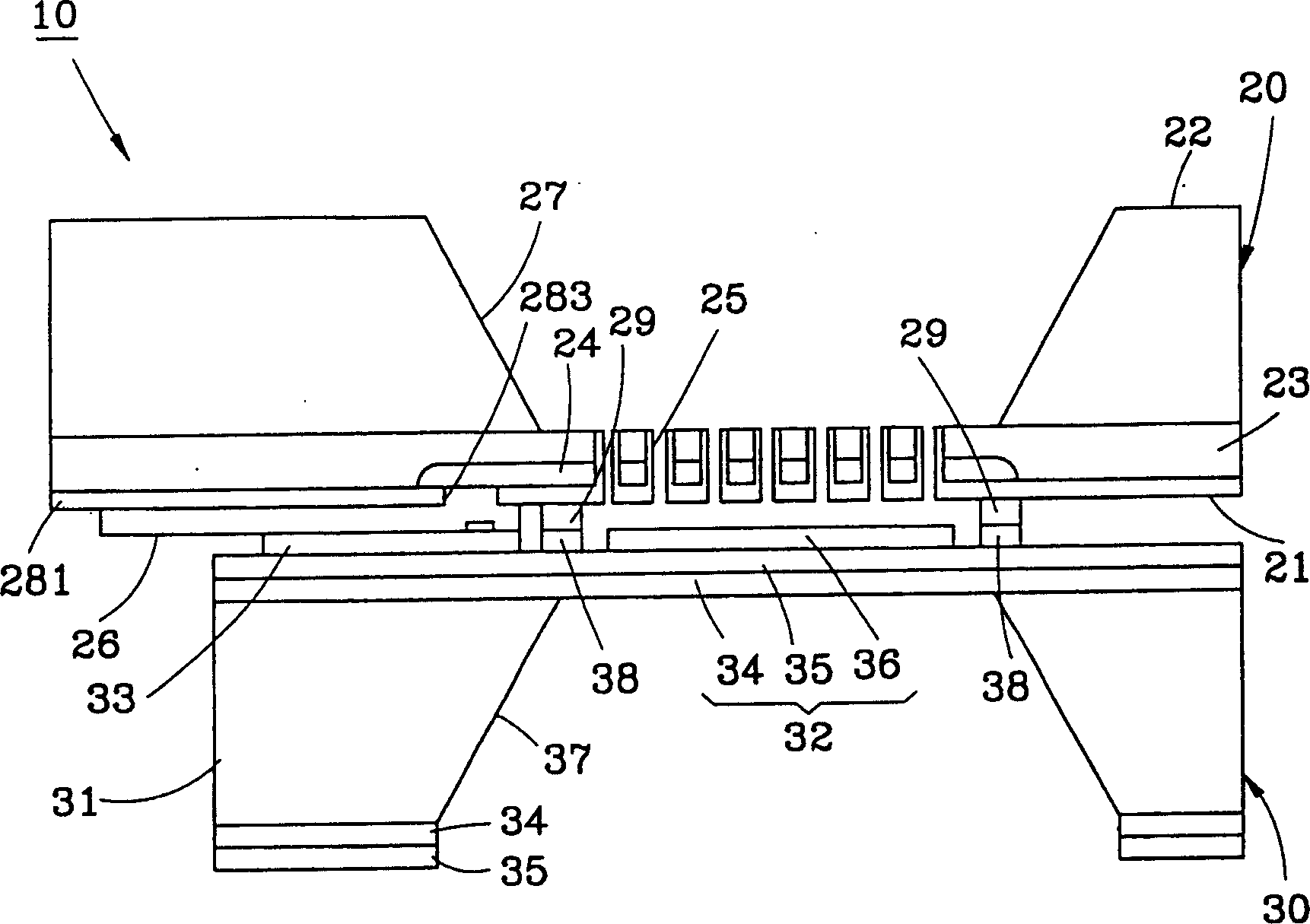
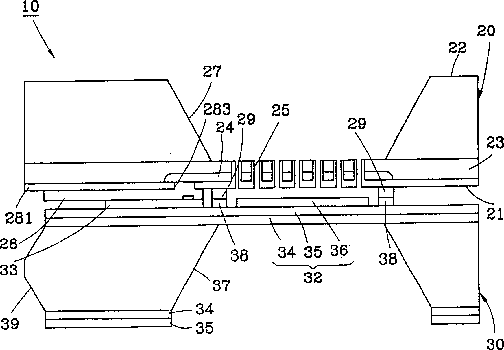
[0021] First, see figure 1 As shown, the present invention provides a capacitive silicon-based micro-microphone 10, which mainly includes a backplane chip 20, and a vibrating chip 30 below the backplane chip 20, wherein:

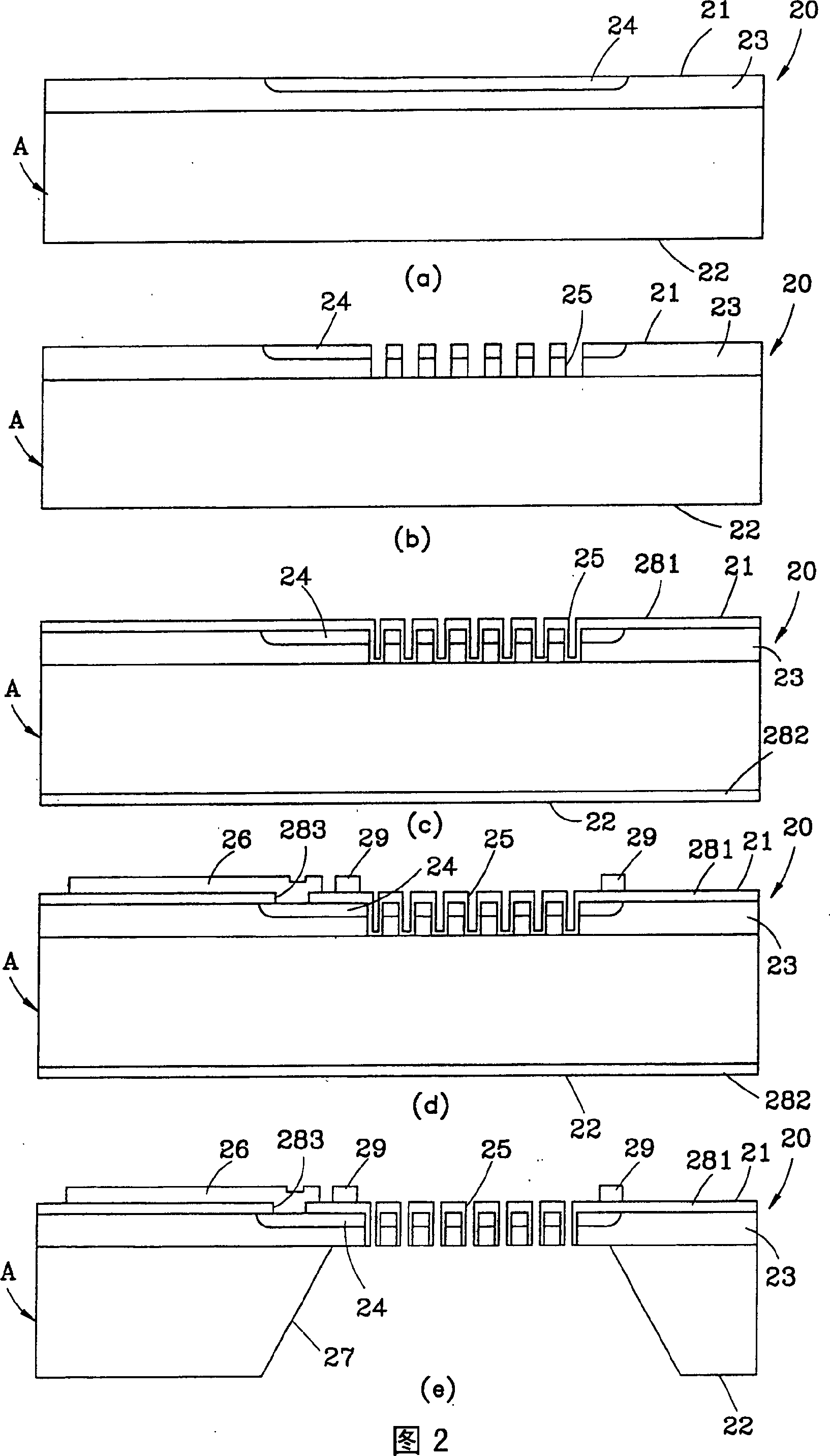
[0022] The backplane wafer 20 has a first surface 21 and a second surface 22 opposite to each other, wherein the first surface 21 is provided with an epitaxial layer 23, a conductive layer 24 doped with P+ ions, a plurality of which penetrate the The epitaxial layer 23 is connected to the sound hole 25 of the conduction layer 24 , and a first electrode 26 electrically connected to the conduction layer 24 , and the second surface 22 defines a resonant groove 27 communicating with the sound holes 25 . Referring to Fig. 2 again, the manufacturing method of the backplane wafer 20 comprises the following steps:

[0023] a. Provide a wafer A with the epitaxial layer 23 on the surface, and then implant P+ ions into the surface of the epitaxial layer 23 to form the...


PUM


Abstract

This invention relates to a condenser silicon-base micro-microphone processed with a micro-electromechanical process, which contains a back board wafer with a sound hole and a vibration wafer with vibrating film to form said micro-microphone by combining said two wafers.

Description

technical field [0001] The invention relates to a capacitive silicon-based micro-microphone and its manufacturing method, which is formed by jointing a backplane chip and a vibrating chip. Background technique [0002] In recent years, the overall development trend of microphone products requires not only thinner and smaller, but also better sensitivity, stability and output performance in order to meet customer needs, which makes the structural design of micro-microphones increasingly complex and diverse. . [0003] Generally, the existing microphone is a single-chip microphone composed of a single chip. The manufacturing method is to first complete a back plate, several sound holes, a base, and a back plate and the base by thin film deposition. sacrificial layer, then etch the base, and remove the sacrificial layer to form a diaphragm, so the dimension design of the microphone will be limited by the thickness of the sacrificial layer, once the thickness of the sacrificial...

Claims


Application Information

Patent Timeline
Patent Type & Authority Applications(China)
IPC IPC(8): H04R19/04
Inventor 李志成邢泰刚魏文杰何鸿钧邱瑞易
Owner MERRY ELECTRONICS CO LTD
Learn More