Flat wire having indication wire and its insertion method

A flat wire and indicator wire technology, applied in the direction of preventing wrong connection of devices, electrical components, coupling devices, etc., can solve problems such as failure of electronic devices and insufficient distance of flat wire insertion.

Inactive Publication Date: 2005-11-16
BENQ CORP
View PDF0 Cites 1 Cited by
  • Summary
  • Abstract
  • Description
  • Claims
  • Application Information

AI Technical Summary

Problems solved by technology

Otherwise, an electronic device may fail if the flat wire is not inserted far enough
In order to overcome the above...

Method used


Image

  • Flat wire having indication wire and its insertion method
  • Flat wire having indication wire and its insertion method
  • Flat wire having indication wire and its insertion method

Examples


Embodiment Construction

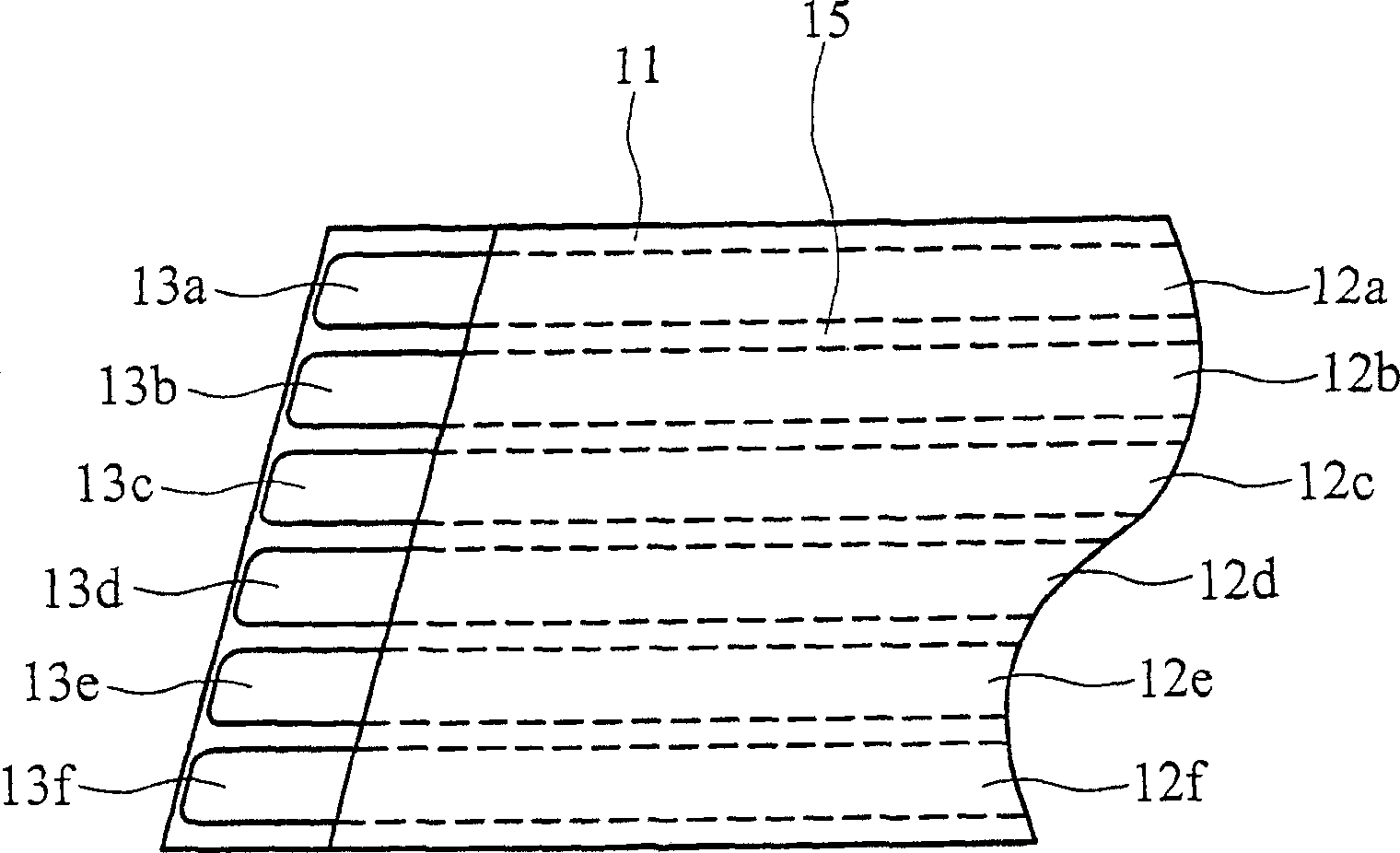
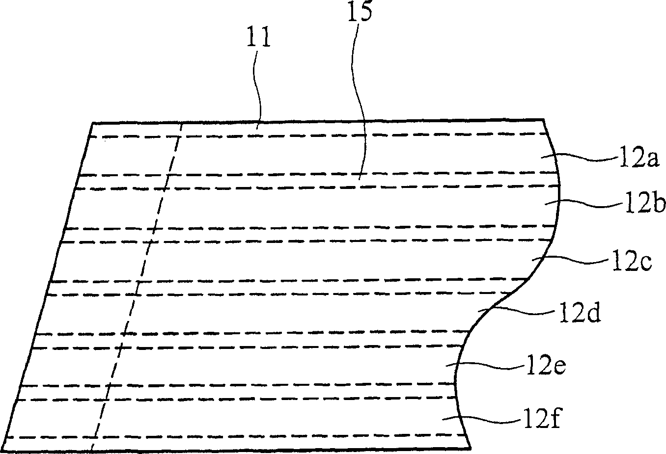
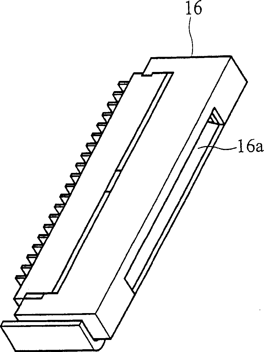
[0024] Figure 3a is a flat line perspective view showing the first embodiment according to the present invention. A flat cable 31, preferably a flexible flat cable (FFC), includes a plurality of transmission lines 32a to 32f, and a flexible plastic insulating layer 35 covering the transmission lines 32a to 32f. And the ends of the transmission lines, such as 33a to 33f, are exposed on a surface. Figure 3b It is a perspective schematic diagram showing the reverse side of the flat wire according to the first embodiment of the present invention. A guide line 37 is formed on one surface of the insulating layer 35, and the guide line is separated from one end of the flat wire 31 by a predetermined distance 37a. Figure 3c is a schematic view showing the connected objects according to the first embodiment of the present invention. A connection object 36 can be disposed on a circuit board (not shown) or a printed circuit board (not shown). The connecting piece 36 has a slot 36a...


PUM


Abstract

RNA interference (RNAi) has become a powerful tool for blocking gene expression in mammals and mammalian cells. This approach requires the delivery of small interfering RNA (siRNA) either as RNA itself or as DNA, using an expression plasmid or virus and the coding sequence for small hairpin RNAs that are processed to siRNAs. Current expression systems for the production of siRNA in vivo rely on RNA polymerase III promoters. These are difficult to regulate and leave most of the RNA in the nucleus of the cell where it is inactive for RNA interference. The invention provides a DNA cassette for the cloning of small hairpin sequences which permit their expression and processing using RNA polymerase II. This system enables efficient transport of the pre-siRNAs to the cytoplasm where they are active and permits the use of regulated and tissue specific promoters for gene expression.

Description

technical field [0001] The invention relates to a connection object, in particular to a flat cable and its insertion method. Background technique [0002] Flexible flat cables are usually used in electronic devices as a connection structure, and the transmission lines in the flexible flat cables are wrapped in polyester film shielding. Flexible cable can be used in a small place for effective connection. For example, a removable device can be connected to a printed circuit board through flexible cables. Flexible flex cables are used in many consumer electronic devices, such as scanners, liquid crystal displays, optical storage devices, and similar devices. [0003] Figure 1a is a schematic representation of an existing flat line perspective. A flat cable 11 includes a plurality of transmission lines 12a to 12f, and a flexible plastic insulating layer 15 covering the transmission lines 12a to 12f. And the ends of the transmission lines, such as 13a to 13f, are exposed on...

Claims


Application Information

Patent Timeline
IPC IPC(8): H01R12/79
Inventor 李庆恭
Owner BENQ CORP
Why Eureka
Try Eureka