Heat pipe radiating unit and manufacturing method thereof

A technology of a heat dissipation device and a manufacturing method, which is applied to tubular elements, heat exchange equipment, indirect heat exchangers, etc., can solve the problems of large thermal resistance, inability to achieve heat dissipation effect, and inability to give full play to the performance of rapid heat conduction of heat pipes. Small size, fast and effective absorption of heat

Inactive Publication Date: 2005-12-07
HONG FU JIN PRECISION IND (SHENZHEN) CO LTD +1
View PDF0 Cites 14 Cited by
  • Summary
  • Abstract
  • Description
  • Claims
  • Application Information

AI Technical Summary

Problems solved by technology

[0004] Although the above-mentioned heat pipe heat dissipation device has improved heat dissipation efficiency compared with the traditional heat dissipation method, the heat pipe and the heat source are connected through the base, and the thermal resistance is relatively large, which cannot give full play to the rapid heat conduction performance of the heat pipe. to the desired cooling effect

Method used


Image

  • Heat pipe radiating unit and manufacturing method thereof
  • Heat pipe radiating unit and manufacturing method thereof
  • Heat pipe radiating unit and manufacturing method thereof

Examples


Embodiment Construction

[0012] The present invention will be further described below in conjunction with the embodiments with reference to the accompanying drawings.

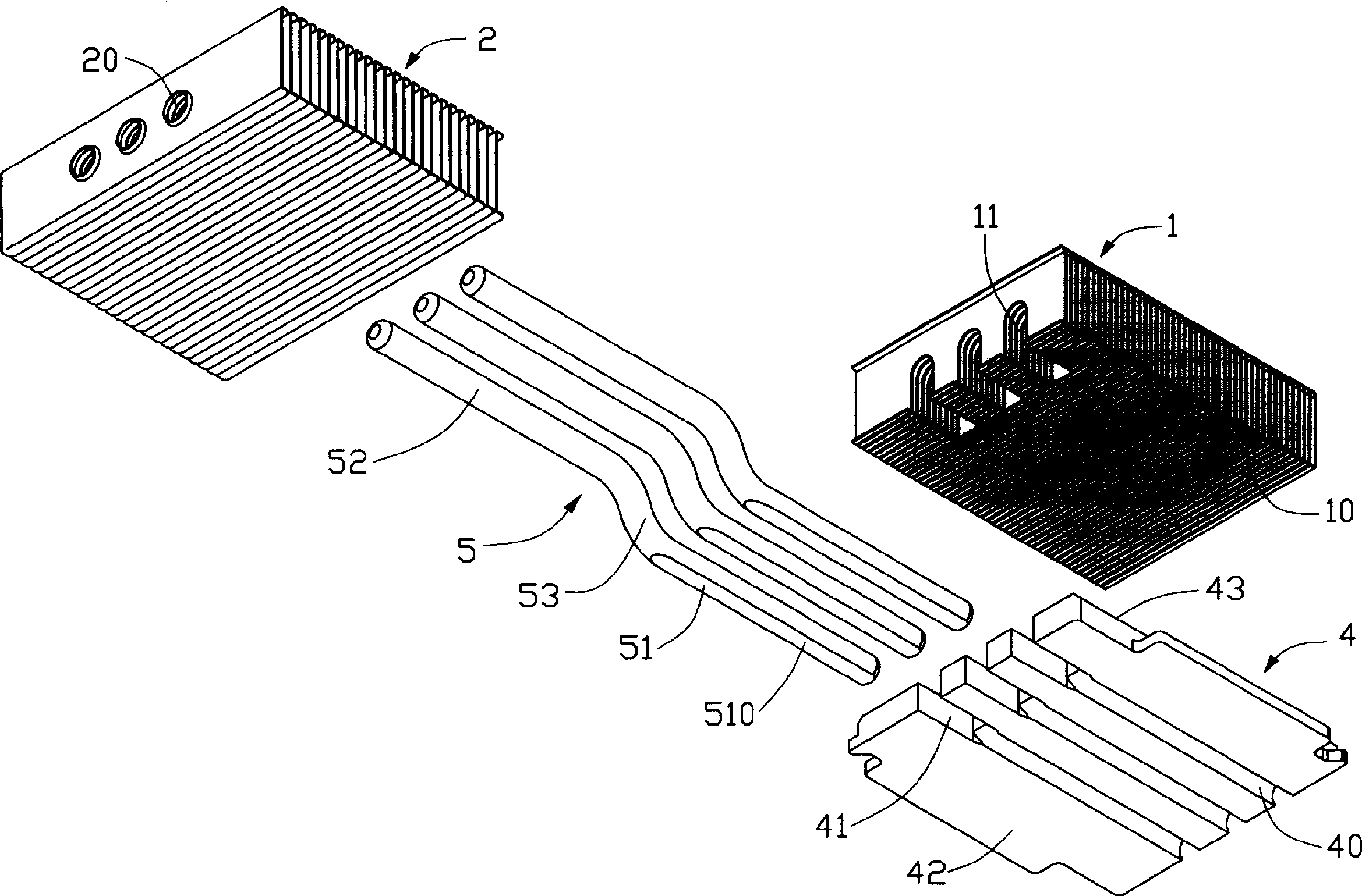
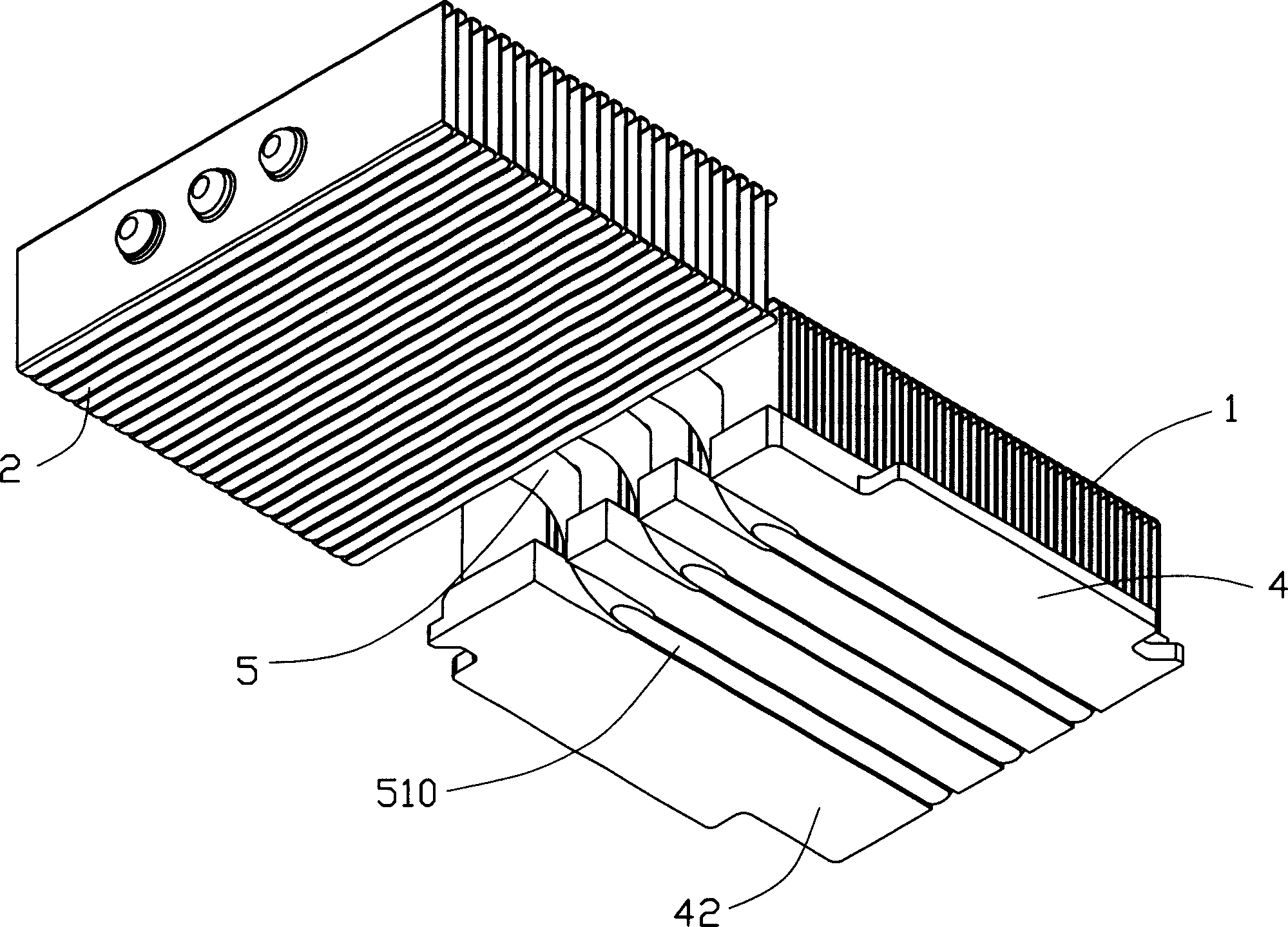
[0013] refer to Figure 1 to Figure 2 , The heat pipe cooling device of the present invention includes two cooling fin groups 1 and 2, a substrate 4 and a heat pipe 5.

[0014] The substrate 4 has an upper surface 43 and a lower surface 42 . The lower surface 42 defines a horizontal groove 40 . One end of the substrate 4 corresponds to the groove 40 and defines a notch 41 . The notch 41 communicates with the groove 40 .

[0015] The heat pipe 5 is cylindrical, and its inner section along the radial direction is circular. The heat pipe 5 includes an evaporating portion 51 , a condensing portion 52 and a bending portion 53 connecting the evaporating portion 51 and the condensing portion 52 . The outer circular surface of the evaporator 51 has a flat surface 510 that is in direct contact with the heating surface of the heat source. The ...


PUM


Abstract

A heat pipe radiation device and making method thereof, which contains substrate, at least one heat pipe and a radiation fins assembly, wherein said heat pipe containing evaporation part and at least condensation part, a channel below substrate for holding the evaporation part which has a plane surface contacted with the heating surface of heat source for quick and effectively absorbing heat, the radiation fins are jointed with condensation part.

Description

【Technical field】 [0001] The invention relates to a heat dissipation device and a manufacturing method thereof, in particular to a heat dissipation device utilizing a heat pipe and a manufacturing method thereof. 【Background technique】 [0002] With the continuous advancement and wide application of large-scale integrated circuit technology, the development of the information industry has advanced by leaps and bounds, and high-frequency and high-speed processors have been continuously introduced. Due to the high-frequency and high-speed operation, the processor generates a lot of heat per unit time. If the heat is not removed in time, the temperature of the processor itself will rise, which will have a great impact on the safety and performance of the system. At present, the problem of heat dissipation has become a problem for every A problem that must be solved when a new generation of high-speed processors is launched. Generally, the industry all installs radiators on chi...

Claims


Application Information

Patent Timeline
Patent Type & Authority Applications(China)
IPC IPC(8): F28D15/00F28D15/02F28F1/32H01L23/427
CPCF28D15/0275F28F1/32
Inventor 盛剑青李孟慈林淑和
Owner HONG FU JIN PRECISION IND (SHENZHEN) CO LTD
Why Eureka
Try Eureka