Method and apparatus for producing a lamp

一种挤压装置、灯管的技术,应用在冷阴极制造、电极系统制造、放电管/灯的制造等方向,能够解决费用昂贵、阴影和干扰等问题,达到改善正面照明、制造简化的效果

Inactive Publication Date: 2005-12-14
PATENT TREUHAND GESELLSCHAFT FUER ELECTRIC GLUEHLAMPEN M B H
View PDF1 Cites 0 Cited by
  • Summary
  • Abstract
  • Description
  • Claims
  • Application Information

AI Technical Summary

Problems solved by technology

[0003] A similar method is also described in US-PS 4,756 701, however, in said method, the contour structure in the tip region is not implemented as precisely as in the background art according to DE 196 23 499 A1
[0004] The disadvantage of these solutions is that an axial protrusion, the so-called extraction tip, is always formed in the top region by the fused extraction tube, which can cause shadows and disturb structures when illuminated from the front
A further disadvantage is that these known methods are relatively expensive, since the extraction tube must first be inserted, cut off in a subsequent working step, and the residual extraction tip closed

Method used


Image

  • Method and apparatus for producing a lamp
  • Method and apparatus for producing a lamp
  • Method and apparatus for producing a lamp

Examples


Embodiment Construction

[0024] The invention is described below with the aid of a low-voltage halogen incandescent lamp. As already mentioned at the outset, the method according to the invention and the device according to the invention are by no means restricted to the application of these lamp types, and are only given here as examples.

[0025] Figure 1 to 3 An embodiment of a halogen incandescent lamp is shown. The halogen incandescent lamp can be configured in a low-voltage working mode or grid voltage, and can be used in a living room or as a lamp in furniture.

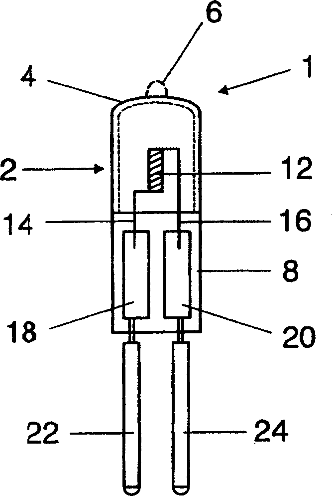
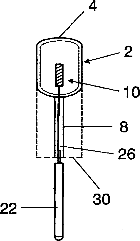
[0026] The incandescent lamp 1 has a lamp tube shell 2, and the lamp tube shell 2 is in an initial state ( figure 2 Shown in dashed lines) has an approximately hollow cylindrical shape with the end formed by a spherically curved tip 4. Unlike traditional halogen incandescent lamps, it does not figure 1 The suction tip 6 shown in dashed lines in the middle forms a smooth plane, which does not hinder the reflection of the end surface. The...


PUM


Abstract

A method and a device for producing a lamp, as well as a lamp produced according to the method, in which the filling of a lamp envelope closed on one side takes place via an inlet opening for the lighting means. The top end of the lamp envelope can thus be smooth without a suction tip.

Description

Technical field [0001] The invention relates to a method according to the preamble of claim 1 for manufacturing lamps, in particular single-sided extruded incandescent lamps, a device for implementing such a method, and a lamp manufactured according to this method. Background technique [0002] For example, the method disclosed in DE 196 23 499 A1 is used, for example, for the production of halogen incandescent lamps. In principle, however, it is also possible to manufacture lamps of other designs, such as discharge lamps, according to this method. In this known method, first, the lamp tube shell has a rounded top end on the end surface, and an axially protruding suction pipe connector is formed on the top end. In addition, the lamp envelope is formed in a mold by blowing an inert gas into the lamp envelope, wherein the bracket on which at least the spiral filament and the current lead are formed is inserted through the open introduction device of the lamp envelope. In addition, ...

Claims


Application Information

Patent Timeline
Patent Type & Authority Applications(China)
IPC IPC(8): H01K1/28H01J9/32H01J9/395H01J9/40H01K1/32H01K1/46H01K1/50H01K3/00H01K3/22H01K3/24H01K3/26
CPCH01J9/326H01J9/395H01J9/40H01K1/325H01K3/22H01K3/24H01K3/26
Inventor C·克里格尔迈尔C·迈尔R·迈尔G·罗森鲍尔
Owner PATENT TREUHAND GESELLSCHAFT FUER ELECTRIC GLUEHLAMPEN M B H
Why Eureka
Try Eureka