

Open-flow powder mill
A powder selection and tailing technology, applied in cement production, grain processing, etc., can solve the problems of reduced mill output, increased unit energy consumption, and reduced economic benefits, so as to improve grinding efficiency, reduce power consumption, and improve powder The effect of grinding efficiency and quality
- Summary
- Abstract
- Description
- Claims
- Application Information
AI Technical Summary
Problems solved by technology
Method used
Image

Examples
example 1
[0038] Example 1: ¢2.4×8.0m open flow grinding:
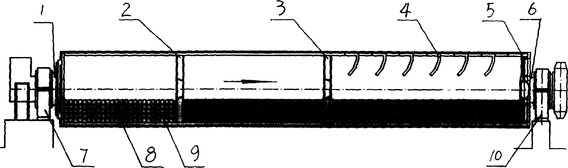
[0039] Such as figure 1 As shown, it includes a rotating cylinder 8, a front bearing seat 7, and a rear bearing seat 10. The front end (grinding head) of the rotating cylinder 8 is connected with the front bearing seat 7 by a bearing, and the tail end of the rotating cylinder 8 is connected by a bearing and The rear bearing housings 10 are connected, and the rotating cylinder 8 is provided with a material inlet 1 and a material outlet 6; the rotating cylinder 8 is fixed with two powder selection devices, a material lifting device, and a finished product control device.
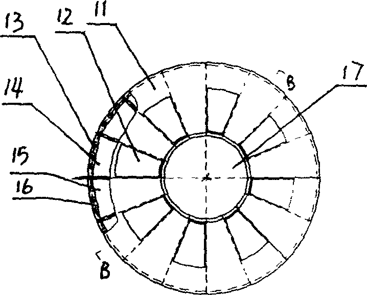
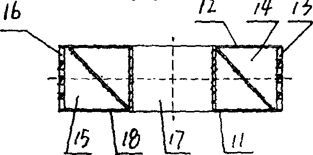
[0040] Such as figure 1 , figure 2 , image 3 , Figure 4 , Figure 5 , Figure 6 , Figure 7 , Figure 8 , Figure 9 , Figure 10 As shown, the powder selection device includes a distribution hopper 11, a drum sieve 19, a wheel belt 25, a feed grate 26, an air distribution device, and a discharge grate 22. The middle part of the distribution hopper ...
example 2
[0065] Example 2: ¢2.6×13m open-flow grinding: basically the same as Example 1, the difference lies in the specific parameters. The specific parameters are as follows:
[0066] The mill is divided into three compartments by 2 sets of powder selection devices, the first set of powder selection device is installed at a distance of 3000mm from the grinding head,
[0067] Feed grate plate 26 is 16 pieces, and the seam width of feed grate seam is 17mm;
[0068] The trommel 19 is 10 pieces, and the hole width of the sieve hole 20 on the trommel 19 is 5.6mm;
[0069] The sub-hopper 11 is 1 piece, and the diameter of the sub-hopper 11 is 900mm;
[0070] The thickness of the air distribution plate 39 of the air distribution device is 4mm, the area of the round hole 40 is 25% of the area of the air distribution plate 39, the diameter of the hole on the air distribution plate is 7mm, and the vortex whirlwind lifting material bar 21 is 8 pieces, forming Arc-shaped, the height of the ...
example 3
[0087] Example 3: ¢3.0×13m open-flow grinding: basically the same as Example 1, the difference lies in the specific parameters.
[0088] The specific parameters are as follows:
[0089] The mill is divided into three compartments by 2 sets of powder selection devices, the first set of powder selection device is installed at a distance of 2250mm from the grinding head,
[0090] Feed grate plate 26 is 20 pieces, and the seam width of feed grate seam is 16mm;
[0091] The trommel 19 is 9 pieces, and the hole width of the sieve hole 20 on the trommel 19 is 6.6mm;
[0092] The sub-hopper 11 is 1 piece, and the diameter of the sub-hopper 11 is 1000mm;
[0093] The thickness of the air distribution plate 39 of the air distribution device is 4mm, the area of the circular hole 40 is 20% of the area of the air distribution plate 39, the diameter of the hole on the air distribution plate is 4mm, and the vortex whirlwind lifting material bar 21 is 10 pieces, forming Arc-shaped, the...
PUM
 Abstract
Description
Claims
Application Information