Internal conmbustion engine valve different lifting device and method thereof

A different lift, internal combustion engine technology, applied in valve drive, valve details, etc., can solve problems such as poor flow capacity, and achieve the effect of improving internal combustion engine performance, combustion speed and fuel economy.

Inactive Publication Date: 2005-12-21
张士强
View PDF0 Cites 11 Cited by
  • Summary
  • Abstract
  • Description
  • Claims
  • Application Information

AI Technical Summary

Problems solved by technology

At present, the structure of double intake valves is mostly used to improve the flow capacity, but the two intake valves move under the same lift, especially when the double intake valves are fully opened, due to the symmetry of the flowing gas in the gasoline engine, each The vortices cancel each other out, and there is almost no large-scale vortex, but only tumble flow. In order to obtain a strong vortex, one of the intake valves must be closed, but the flow capacity is worse than that of the double intake valves. The above-mentioned prior art is insufficient The point is: the same lift of the two intake valves sacrifices the swirl to ensure the flow, and the single opening of one intake valve sacrifices the flow to obtain the swirl

Method used


Image

  • Internal conmbustion engine valve different lifting device and method thereof
  • Internal conmbustion engine valve different lifting device and method thereof
  • Internal conmbustion engine valve different lifting device and method thereof

Examples


Embodiment 1

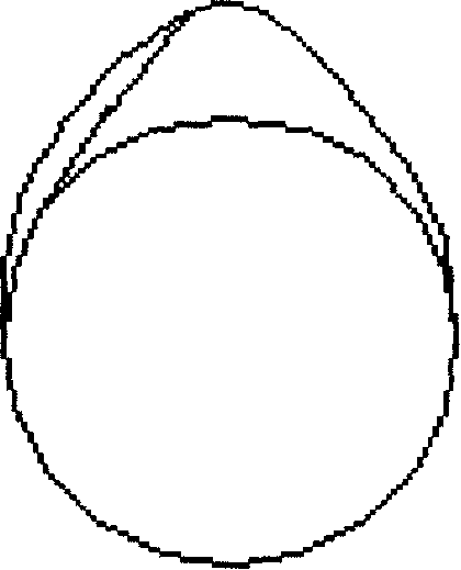
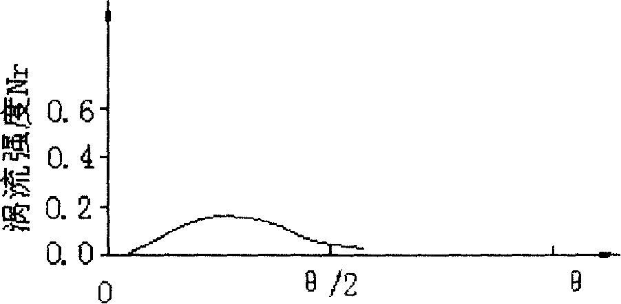
[0052] As shown in Figure 1 (A), it includes a symmetrical profile cam and an asymmetrical profile cam or two asymmetrical profile cams, the maximum lift height of the symmetrical profile cam and the asymmetrical profile cam is the same, and is set on the cam The maximum lift points on the axial projection of the group of cams on the shaft coincide; the two intake valves are driven by the two intake cams on the camshaft, and the opening lifts are different, and the closing lifts are the same; the valve opening process There is lift difference and large-scale eddy current, which weakens from weak to strong; there is no lift difference in the valve closing process, but due to the eddy current inertia at the beginning of closing, the large-scale eddy current disappears after a short period of time delay, as shown in Fig. 1(B) The lift effect of Embodiment 1 has been obtained.

Embodiment 2

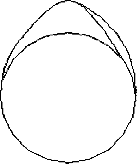
[0054] As shown in Figure 2 (A), it includes a symmetrical profile cam and an asymmetrical profile cam or two asymmetrical profile cams, the maximum lift height of the symmetrical profile cam and the asymmetrical profile cam is the same, and is set on the cam The maximum lift point on the axial projection of the group of cams on the shaft coincides; the two intake valves are driven by the two intake cams on the camshaft, the opening lift is the same, and the closing lift is different; when the valve is opened Since there is no lift difference and large-scale vortex in the process, there is a lift difference in the process of valve closing, and large-scale vortex is generated, which changes from weak to strong and then weakens to disappear. Figure 2 (B) shows the second embodiment lift effect. The difference between the second embodiment and the first embodiment is that the device used in the first embodiment makes the valve opening lifts different and the closing lifts the sam...

Embodiment 3

[0056] As shown in Figure 3, it includes two asymmetric profile cams, the maximum lift height of the two asymmetric profile cams is the same, and the maximum lift point on the axial projection of the group of cams arranged on the camshaft is non-symmetrical. In the overlapping position, the two asymmetric profile cams are symmetrically distributed on the axial projection; the two intake valves are driven by the two intake cams on the camshaft, and the opening lifts are different, and the closing lifts are different (Except for a point with the same lift); there are large-scale eddy currents during the valve opening process and the valve closing process. Due to the same lift point in the middle process and the influence of eddy current inertia, the large-scale The scale vortex will gradually disappear, and then the large-scale vortex will appear again due to the increase of the lift difference. Because the magnitude of the vortex intensity of the two intake valves changes, the d...


PUM


Abstract

The invention discloses a combustion air valve different raising device which improves the air channel and the flow inside the cylinder, which is a set of cam includes a symmetric jam and a non-symmetric jam or two non symmetric jams; or includes a symmetric jam and a non-symmetric jam or two non symmetric jams. The maximum raising point on the axial project is a non doubling position, above two non-symmetric jam is symmetric at axial projection; each group of jams has the same maximum raising. The invention also discloses the actualizing method with above device.

Description

technical field [0001] The invention relates to a valve movement method of an internal combustion engine and a device for realizing the method, in particular to a method for moving a valve of an internal combustion engine with two intake valves and a device for realizing the method. Background technique [0002] The combustion of the internal combustion engine is one of the main factors causing air pollution. Its harm to human health and the environment has been widely concerned by people, and reducing the emission and fuel consumption of internal combustion engines has become a worldwide issue. The air movement in the cylinder of the internal combustion engine has a decisive influence on the formation of the mixture and the combustion process, and also affects the power, economy, combustion noise and harmful gas emissions of the internal combustion engine. Well-organized in-cylinder air movement is an effective way to meet increasingly stringent emissions and fuel economy ...

Claims


Application Information

Patent Timeline
Patent Type & Authority Applications(China)
IPC IPC(8): F01L1/08
Inventor 张士强
Owner 张士强
Why Eureka
Try Eureka