Optical fiber weighing system

A weighing system and optical fiber technology, applied in the field of micro-bending optical fiber weighing sensing system, to achieve the effect of low cost, remote alarm and monitoring

Inactive Publication Date: 2005-12-21
烟台艾森信息技术股份有限公司
View PDF0 Cites 9 Cited by
  • Summary
  • Abstract
  • Description
  • Claims
  • Application Information

AI Technical Summary

Problems solved by technology

[0004] In order to overcome the deficiencies of the existing weighing sensor system, the present invention provides a new generation of optical fiber weighing sensor system

Method used


Image

  • Optical fiber weighing system
  • Optical fiber weighing system

Examples


Embodiment Construction

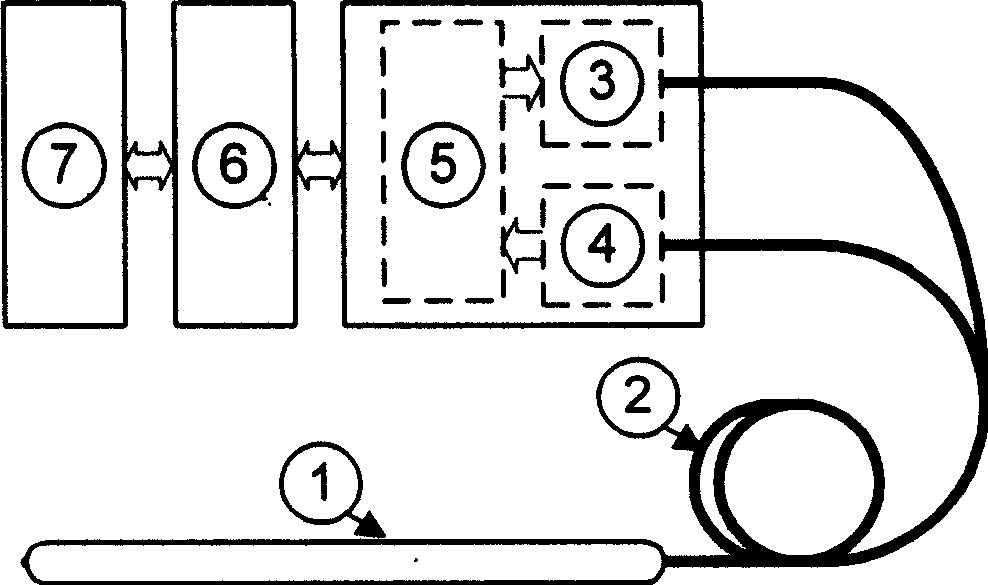
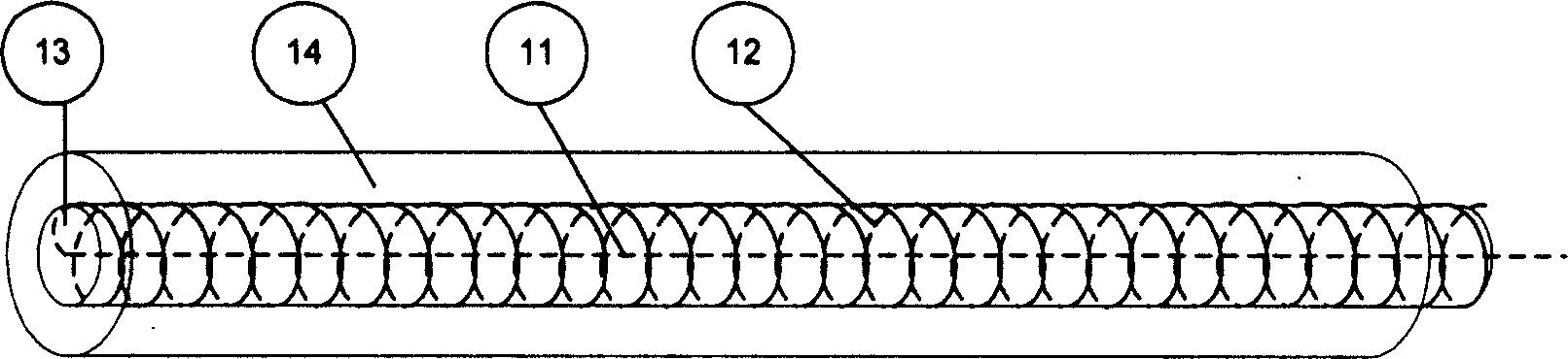
[0010] The microbending fiber optic load cell 1 is connected to the light emitter 3 and the light receiver 4 through the optical fiber 2 that conducts the light signal. The signal is converted into an electrical signal, and the optical transmitter 3 and the optical receiver 4 are respectively connected to an optical transceiver driving circuit 5, and the optical transceiver driving circuit 5 is connected to a high-speed analog converter 6, and the high-speed analog converter 6 is connected to the digital signal The data processing system 7 for data processing and compensation is connected; wherein the microbending optical fiber load cell 1 is packaged on the axis of a resin rod 13 for a part 11 of the optical fiber, and the other part 12 of the optical fiber is wound on the surface of the resin rod 13 and wrapped with another resin rod. Barrel 14 is protected.


PUM


Abstract

An optical fiber weighing system features connecting slightly bended optical weighing transducer to light emitter and receiver through optical fiber ,emitting constant light signal by light emitter , converting weight light signal to be electric signal by light receiver , connecting said emitter and receiver to light transceiver driving circuit separately and connecting this driving circuit to high speed analog converter being connected with data processing system where digital signal is processed and compensated .

Description

technical field [0001] The invention and a micro-bending optical fiber weighing sensor system can realize rapid weighing in various harsh environments and inflammable and explosive environments, and can also realize portability and remote monitoring. Background technique [0002] Currently known weighing sensor systems are mainly electronic weighing sensor systems. This electronic system is difficult to use in strong electromagnetic fields, strong corrosion, flammable and explosive application environments. For applications with high humidity, the system must be equipped with a vacuum seal. The shortcomings of the existing electronic weighing sensor system include low anti-interference ability, complex mechanism, high cost, slow response speed, etc. At the same time, this electronic weighing sensor system generally needs to be equipped with a metal table, so the volume and weight are relatively large. Large, especially bad for portable applications. [0003] Optical fiber...

Claims


Application Information

Patent Timeline
Patent Type & Authority Applications(China)
IPC IPC(8): G01G9/00
Inventor 梁少华
Owner 烟台艾森信息技术股份有限公司
Why Eureka
Try Eureka