High-voltage network high-capacity powerfree compensation continuous regulation method

A technology of high-voltage power grid and adjustment method, which is applied in the direction of reactive power compensation, reactive power adjustment/elimination/compensation, etc., can solve the problems of power grid impact, large impact current, and the service life of switching switches cannot meet actual needs, etc., to achieve The effect of prolonging the working life and avoiding shock

A technology of high-voltage power grid and adjustment method, which is applied in the direction of reactive power compensation, reactive power adjustment/elimination/compensation, etc., can solve the problems of power grid impact, large impact current, and the service life of switching switches cannot meet actual needs, etc., to achieve The effect of prolonging the working life and avoiding shock

CN1710772AInactive Publication Date: 2005-12-21SHANGHAI JIAO TONG UNIV

Image

  • High-voltage network high-capacity powerfree compensation continuous regulation method
  • High-voltage network high-capacity powerfree compensation continuous regulation method

Examples


Embodiment Construction

[0029] In order to better understand the technical solution of the present invention, the technical solution of the present invention will be further described in detail below in conjunction with the accompanying drawings and embodiments.

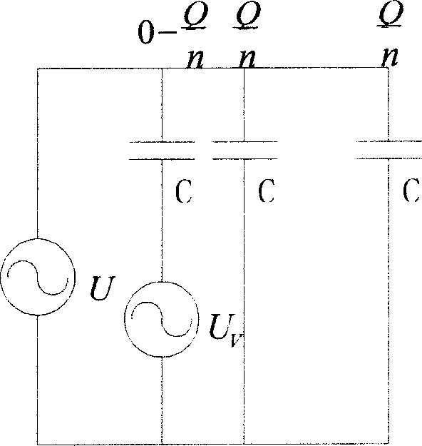
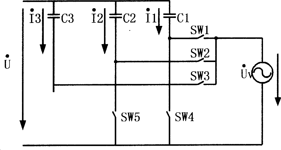
[0030] The principle of the present invention to realize the continuous adjustment of reactive power compensation is as follows: figure 1 As shown, the large-capacity reactive power compensation continuous regulation circuit of the high-voltage power grid is composed of n reactive power compensation branches, one of which connects the fixed capacitor C with the variable voltage source U v connected to provide 0-Q / n continuously regulated reactive power, while the other n-1 compensation branches connect the fixed capacitor C to the power supply U to provide fixed reactive power Q / n, by compensating the first The continuous adjustment of the branch and the switching of other compensation branches can realize the continuous adjustment of syste...


PUM


Abstract

Provided total reactive power Q requested by system is supplied by n pieces of reactive compensation branch. A fixed capacitor is connected to a variable voltage source in one piece of compensation branch to supply 0-Q / n continuous controlled reactive power. Other n-1 pieces of compensation branch connect fixed capacitor to power source to supply fixed reactive powers. System reactive power is continuous controlled from 0-Q by continuous controlling reactive power in first piece of compensation branch and switching to other compensation branches. The capacity Qv of variable voltage source is only 1 / 4n of Q. Switching operation is implemented at time of zero current of all capacitors in n pieces of reactive compensation branch in order to avoid impulsion from electric network. Features are: low cost to realize reactive continuous control for electric network in high voltage, and prolonging service life of capacitor and switches.

Description

technical field [0001] The invention relates to a large-capacity reactive power compensation continuous adjustment method for a high-voltage power grid, which can be used for reactive power compensation of a 6KV and above power grid, and belongs to the technical field of electric power systems. Background technique: [0002] At present, the main methods of reactive power compensation for 6KV and above power grids at home and abroad are as follows: [0003] 1) Provide capacitive reactive power for the power system through capacitor switching to improve the power factor of the power supply system. [0004] 2) By adjusting the conduction angle of the thyristor, the magnitude of the current passing through the inductor can be changed, and the size of the inductive reactive power can be adjusted to maintain the stability of the grid voltage. [0005] But this traditional method has the following outstanding problems: [0006] 1) Capacitor switching of large-capacity reactive po...

Claims


Application Information

Patent Timeline
21 Dec 2005
Publication
CN1710772A
IPC
H02J3/18
CPC
Y02E40/30
Inventors
εΆθŠƒη”Ÿ; ιƒ‘η›Šζ…§