Intelligent antenna downstream wave-packet formation method combined with space hour block coding

A space-time block coding and smart antenna technology, applied in diversity/multi-antenna systems, space transmit diversity, etc., can solve problems such as bit error rate fluctuations and unstable system performance

Inactive Publication Date: 2005-12-21
HARBIN INST OF TECH
View PDF0 Cites 17 Cited by
  • Summary
  • Abstract
  • Description
  • Claims
  • Application Information

AI Technical Summary

Problems solved by technology

[0025] The purpose of the present invention is to provide a smart antenna downlink beamforming method combined with space-time block coding, to overcome the large fluctuations in the bit erro

Method used


Image

  • Intelligent antenna downstream wave-packet formation method combined with space hour block coding
  • Intelligent antenna downstream wave-packet formation method combined with space hour block coding
  • Intelligent antenna downstream wave-packet formation method combined with space hour block coding

Examples


specific Embodiment approach 1

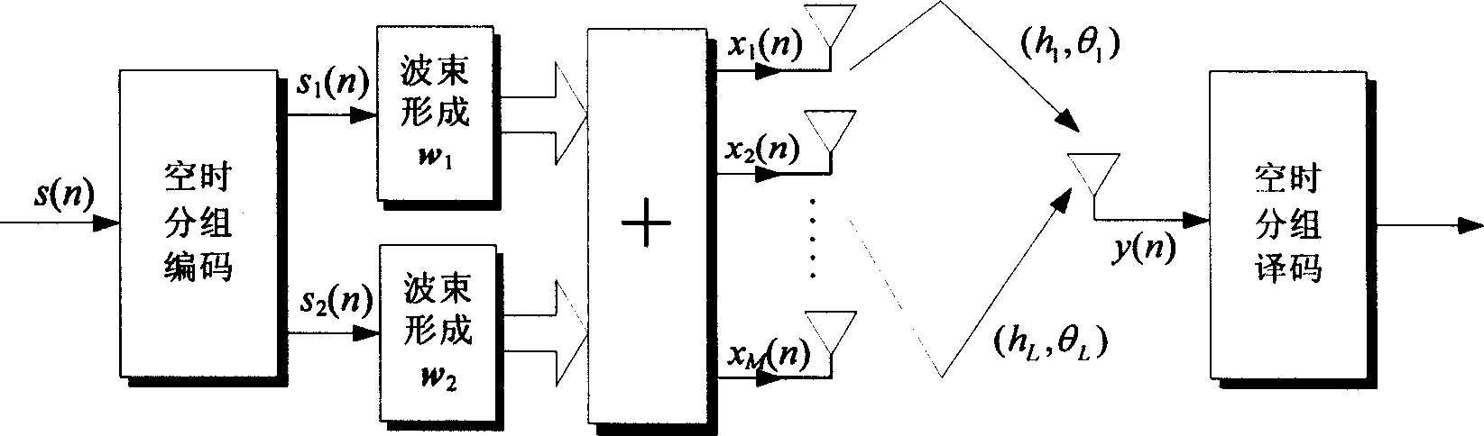
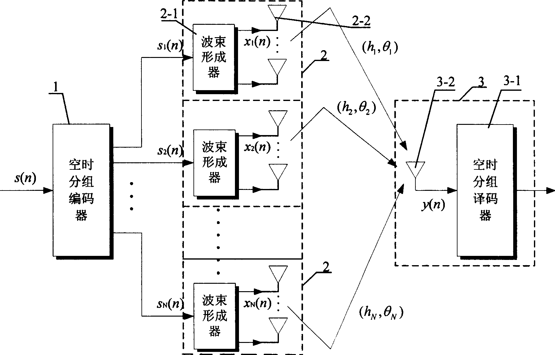
[0028] Specific implementation mode one: the following combination Figure 2 to Figure 8 This embodiment will be specifically described. The equipment used in this embodiment is composed of a space-time block coder 1, N beamforming units 2 and a mobile station 3, and each beamforming unit 2 is composed of a beamformer 2-1 and M base station antennas 2-2 , the mobile station 3 is composed of a space-time block decoder 3-1 and at least one mobile station antenna 3-2, and the distance between two adjacent base station antennas 2-2 arranged in the same beamforming unit 2 is less than or equal to The carrier wavelength of the signal transmitted by half of the base station antenna 2-2, the distance between two adjacent beamforming units 2 is greater than or equal to ten times the carrier wavelength of the signal transmitted by the base station antenna 2-2, the method is realized through the following steps: 1. Input The signal s(n) first passes through the space-time block encoder ...

specific Embodiment approach 2

[0040] Specific implementation mode two: the following combination figure 2 This embodiment will be specifically described. The difference between this embodiment and the first embodiment is that: in step one, the space-time block encoder 1 selects the Alamouti STBC scheme for encoding. Among many space-time coding schemes, the coding efficiency of the Alamouti STBC (Alamouti is the name of a foreign scholar, Alamouti STBC can be translated as Alamouti space-time block coding) scheme is 1, compared with the uncoded system, it can maintain the same Under the premise of increasing the bandwidth of the system, it can improve the spectrum utilization rate of the system. It has been widely used because of its simple coding and decoding, effectiveness and unit coding efficiency. Introducing the beamforming technology into the Alamouti STBC system can make up for the deficiency of this low-order space-time block coding, obtain beamforming gain and diversity gain at the same time, a...


PUM


Abstract

Equipment utilized in the method includes time-space block encoder (1), N pieces of beam-forming unit (2), and mobile station (3). (2) is composed of beam shaper and M pieces of base station antenna. (3) is composed of time-space block encoder and at least one mobile station antenna. Distance between two antennas of adjacent base stations setup inside same beam-forming unit is less than ad equal to half wavelength of carrier wave of transmitting signal of (2). Distance between two adjacent (2) larger than and equal to ten times of wavelength of carrier wave of transmitting signal of (2). Implementing steps are as following: passing through (1), input signal generates N routes output signals; beam shaper carries out weighting for the output signal so as to output weighted signal; through base station antenna, weighted signal is transmitted out; decoding is carried out. Invention overcomes disadvantages of larger fluctuation of error rate when DOA signal and angle expansion are varied.

Description

Technical field: [0001] The invention relates to a method for forming a downlink beam of a smart antenna, in particular to a method for forming a downlink beam of a smart antenna combined with space-time block coding. Background technique: [0002] In wireless communication systems, co-channel interference (CCI) and intersymbol interference (ISI) are two main factors that limit communication capacity and data transmission rate. The third generation of wireless communication mainly adopts code division multiple access (CDMA) technology to improve communication capacity and data transmission rate. The CDMA system is an interference-limited system, which is limited by multipath fading, multiple access interference (MAI) and intersymbol interference (ISI) of the wireless channel. Improving the user's signal-to-noise ratio cannot be achieved simply by increasing the transmitter power. Therefore, Multi-antenna and space-time processing techniques have become important research to...

Claims


Application Information

Patent Timeline
IPC IPC(8): H04B7/06
Inventor 孟维晓古磊徐玉滨
Owner HARBIN INST OF TECH
Why Eureka
Try Eureka