Fluidized-bed gasification furnace

A fluidized bed gasifier and fluidized bed technology are applied in the field of fluidized bed gasifiers and can solve problems such as disadvantages

Inactive Publication Date: 2005-12-21
EBARA CORP
View PDF2 Cites 5 Cited by
  • Summary
  • Abstract
  • Description
  • Claims
  • Application Information

AI Technical Summary

Problems solved by technology

However, it has been found that a gasifier with a hearth of circ

Method used


Image

  • Fluidized-bed gasification furnace
  • Fluidized-bed gasification furnace
  • Fluidized-bed gasification furnace

Examples


Embodiment Construction

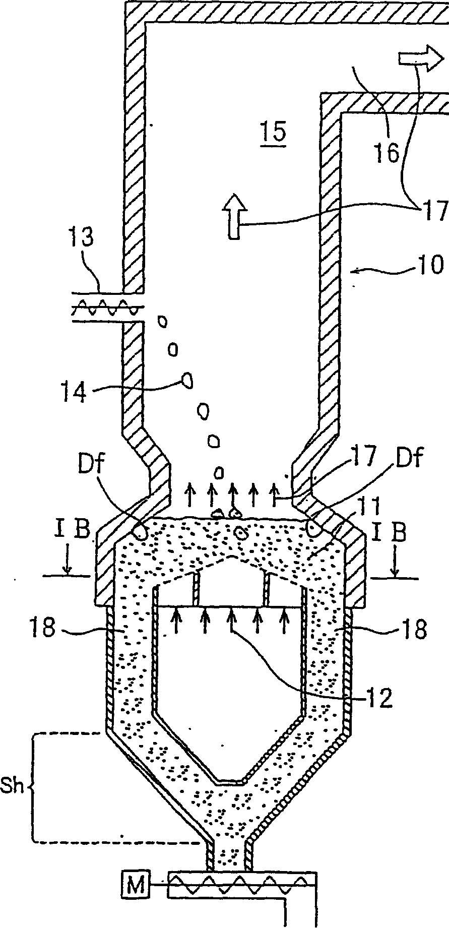
[0072] A fluidized bed gasifier according to an embodiment of the present invention will be described in detail below with reference to the accompanying drawings. Embodiments of the present invention will be described in comparison with conventional structures.

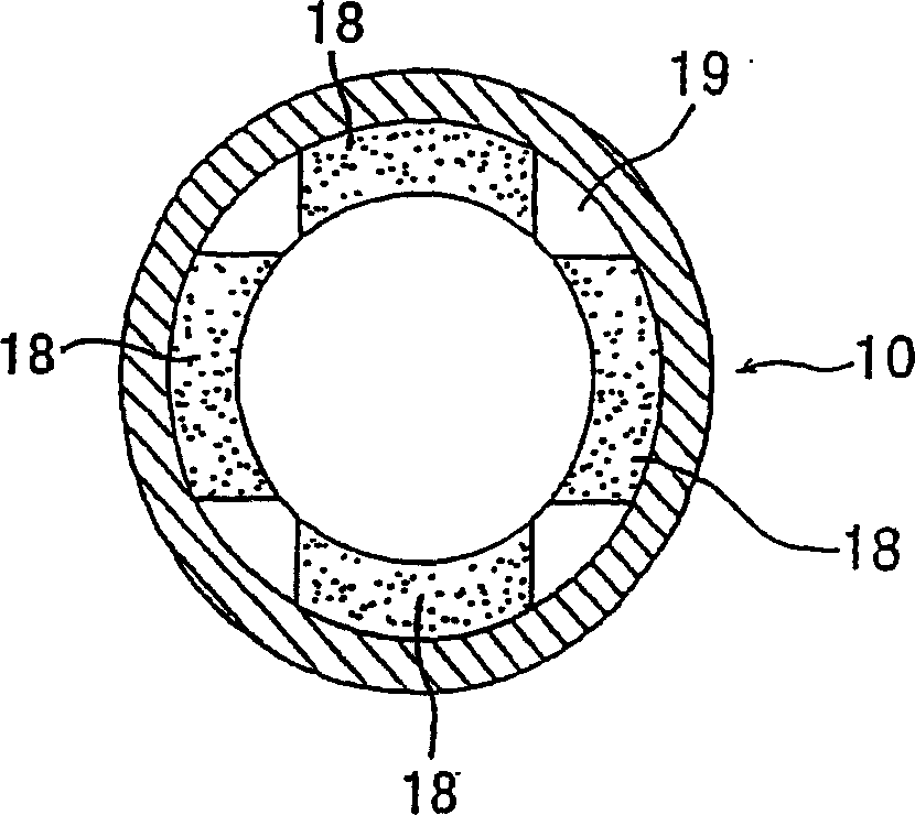
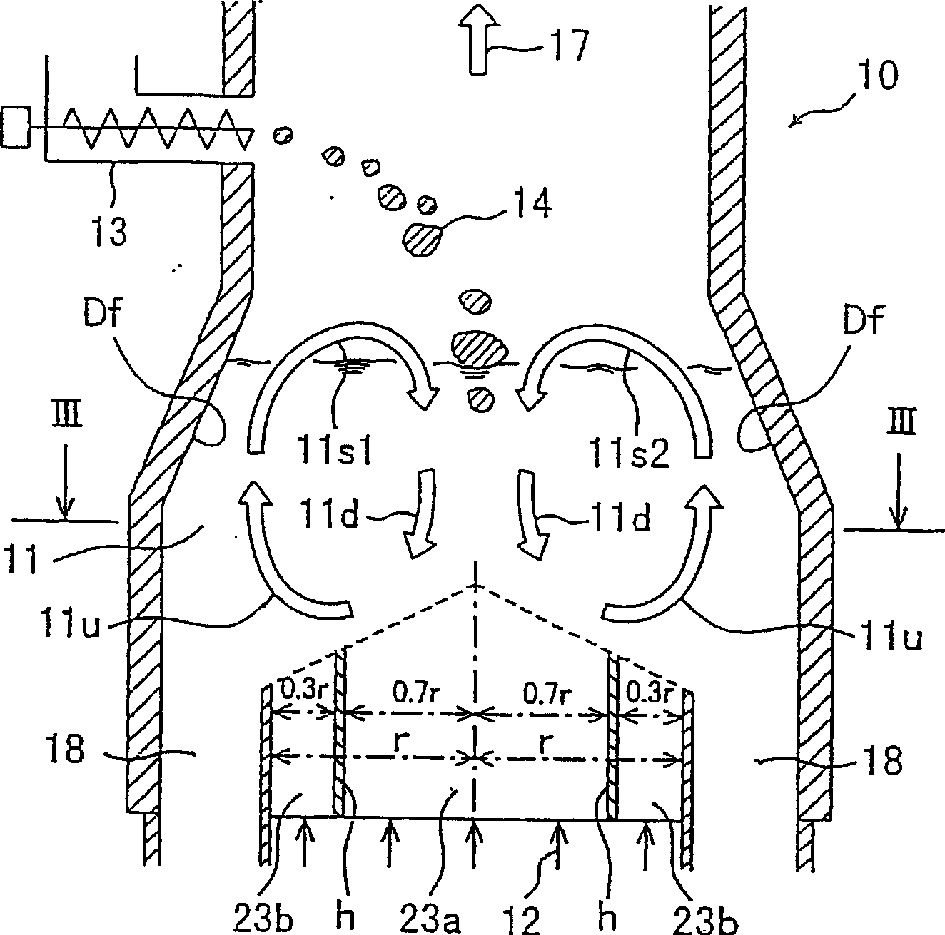
[0073] Figures 1A to 3 is a view of the overall structure of a conventional fluidized bed gasifier. Figure 1A is the vertical section view, Figure 1B along Figure 1A A cross-sectional view taken along the line IB-IB. figure 2 yes Figure 1A Magnified view of hearth area shown. image 3 is along figure 2 Sectional view taken on line III-III in

[0074] Such as Figures 1A to 3 As shown, a fluidized bed gasifier 10 has a fluidized bed 11 at its lower portion, in which a fluidizing medium such as silica sand is fluidized by introducing (ie, blowing) a fluidizing gas from the bottom of the fluidized bed gasifier 10 . In the fluidized bed (fluidized bed) 11, the descending fluidized bed 11d moving downward from...


PUM


Abstract

The present invention relates to a fluidized-bed gasifier used in a gasification and slagging combustion system, which is used for gasifying combustibles, and the generated gas and coke are transported to the slagging combustion furnace, and in the slagging combustion furnace, a high temperature The gas and coke are burnt down and the ashes are melted. The fluidized bed gasifier comprises a fluidized bed (11) having a substantially rectangular horizontal cross-section in which combustibles are gasified in a circulating flow of fluidized medium, and at least one non-conductive bed defined on at least one side of the fluidized bed The combustible material discharge part (18) is used to discharge the fluidized medium and the non-combustible material accompanying the fluidized medium.

Description

technical field [0001] The present invention relates to a fluidized bed gasifier used in a gasification and slagging combustion system for gasifying combustibles, including municipal waste, industrial waste, biomass, etc., which will generate gas and coke (solid carbon ) to the slagging furnace, where the gas and coke are burned at high temperature and the ash is melted. Background technique [0002] In recent years, a method has been adopted to gasify (pyrolyze) waste such as municipal waste, industrial waste, biomass or medical waste in a reducing atmosphere in a fluidized bed gasifier, and the gas, coke and ash produced by the gasification A slagging furnace (melting furnace) is introduced, and gas and coke are burned at high temperature and ashes are melted in the slagging furnace. [0003] For example, a conventional fluidized bed gasifier is disclosed in Japanese Patent Laid-Open Publication No. 2-147692. In the fluidized-bed gasifier disclosed in this document, by m...

Claims


Application Information

Patent Timeline
IPC IPC(8): F23C10/24
Inventor 石川龙一乡家千贺男小杉茂长洋光
Owner EBARA CORP
Why Eureka
Try Eureka