Supercharge Your Innovation With Domain-Expert AI Agents!

Magnetic resonance imaging apparatus

一种磁共振成像、倾斜磁场的技术,应用在磁共振测量、测量装置、测量磁变量等方向,能够解决振动困难等问题,达到降低空气传播振动即噪音的效果

Inactive Publication Date: 2005-12-28
HITACHI LTD +2
View PDF2 Cites 0 Cited by
  • Summary
  • Abstract
  • Description
  • Claims
  • Application Information

AI Technical Summary

Problems solved by technology

However, even in the structure of this patent document 2, the vibration from the GC is transmitted to the outside through the GC supporting part, and as a result, it is difficult to suppress the vibration from the GC.

Method used


Image

  • Magnetic resonance imaging apparatus
  • Magnetic resonance imaging apparatus
  • Magnetic resonance imaging apparatus

Examples


Embodiment 1

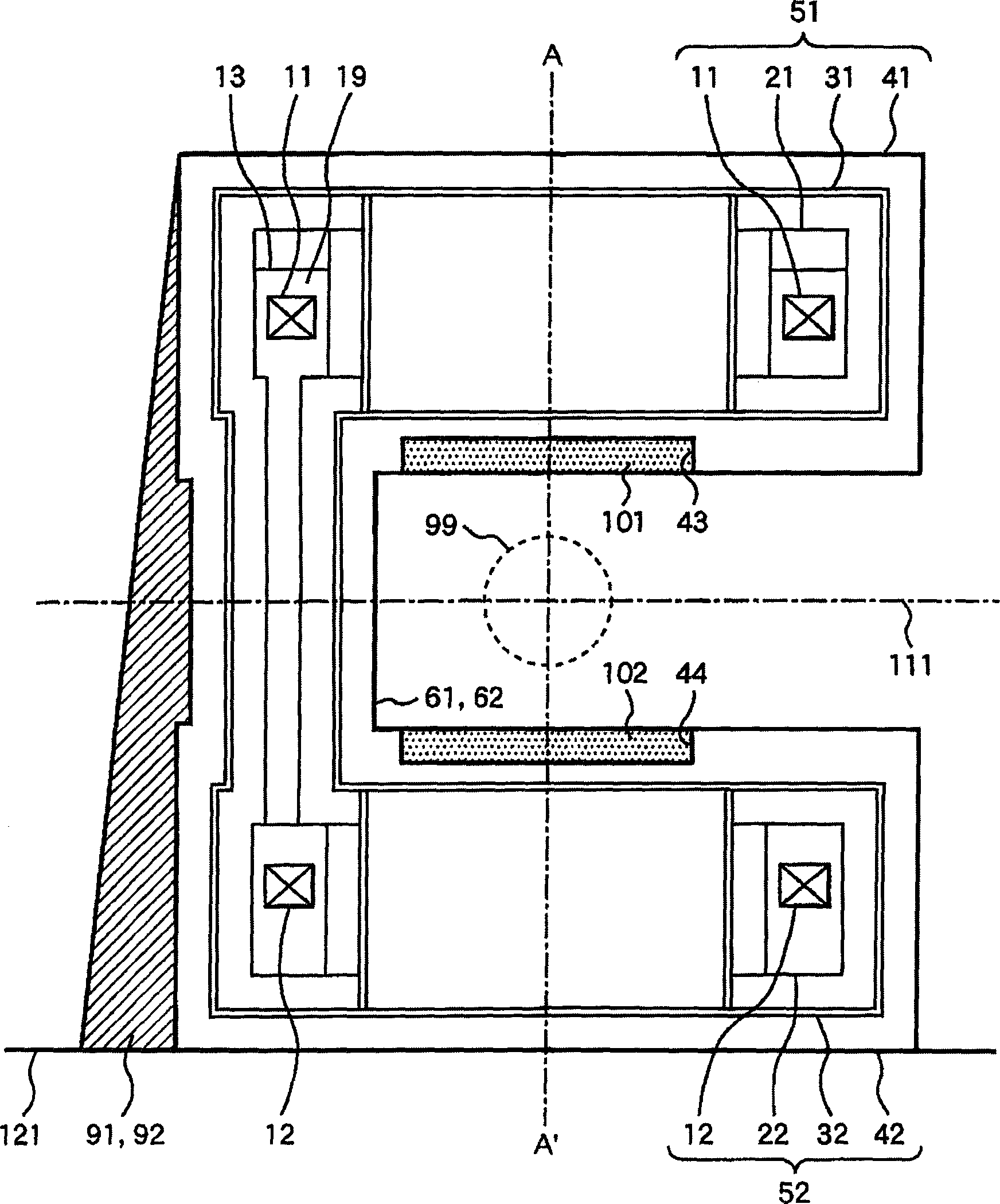
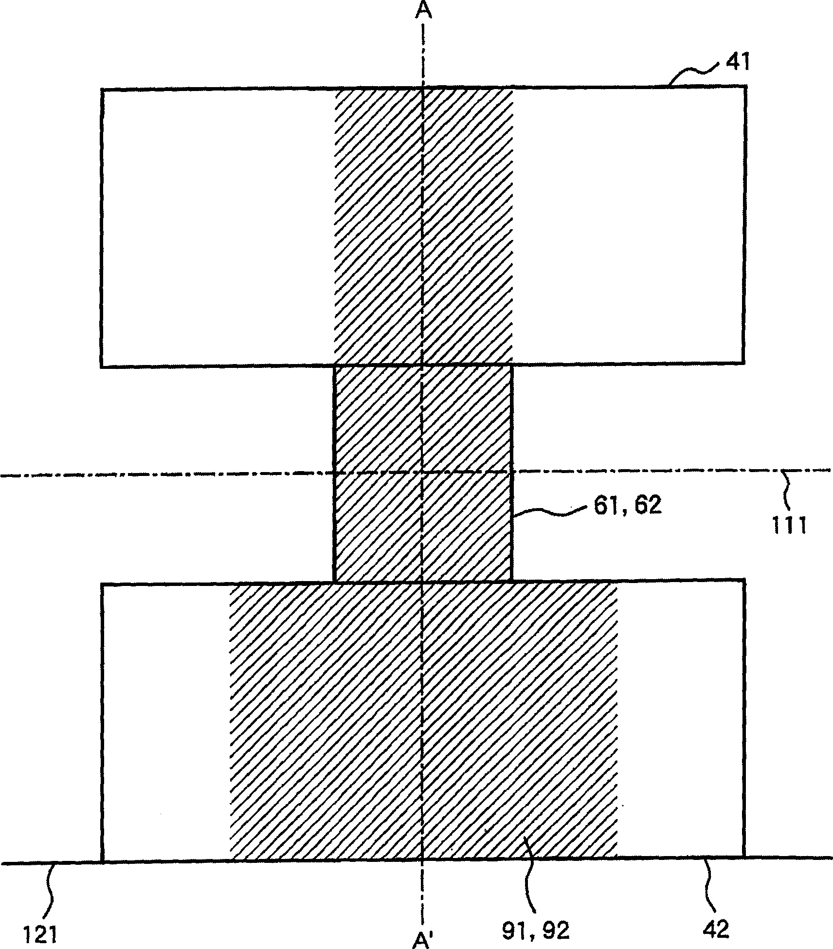
[0025] figure 1 A cross-sectional view showing the MRI apparatus according to the first embodiment of the present invention. The superconducting magnet device 80 of this embodiment has cryostats 51 , 52 and connecting pipes 61 , 62 connecting the cryostats 51 , 52 . The cryostats 51, 52 are arranged facing each other, and include superconducting coils 11, 12 which are ring coils through which a predetermined current flows in order to generate a static magnetic field, and a circle containing the superconducting coils together with liquid He as a refrigerant. Cylindrical coil containers 21, 22 are provided with annular cylindrical heat barriers 31, 32 surrounding the coil containers, and cylindrical vacuum chambers that surround the coil containers 21, 22 and the thermal barriers 31, 32 and maintain a vacuum inside. Containers 41,42. In addition, the cryostat 52 is bolted to the floor 121 via a fixing member (not shown). In addition, reference numeral 13 in the figure represe...

Embodiment 2

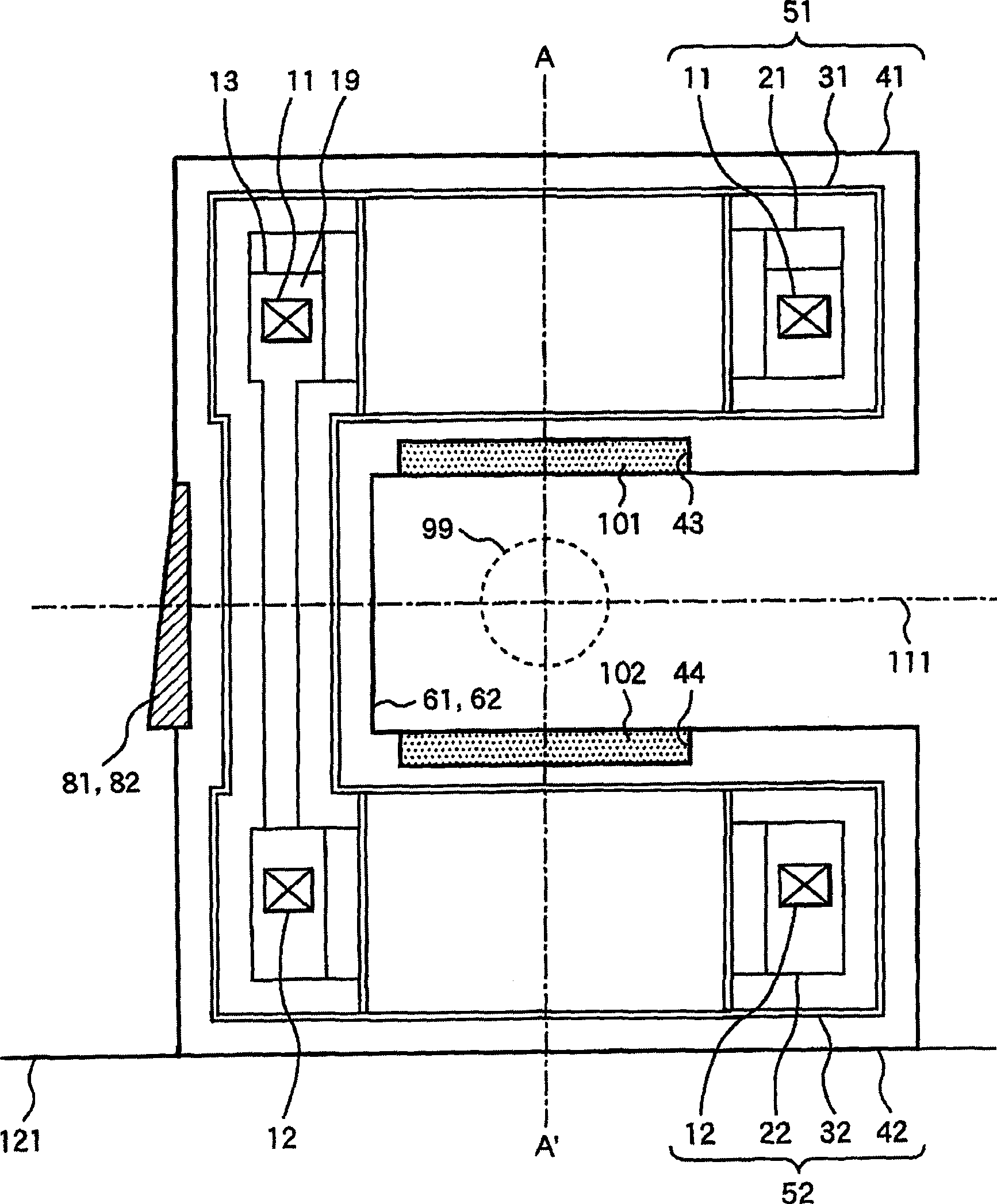
[0036] image 3 Shows the second embodiment of the present invention. The difference between this embodiment and the first embodiment is that only the connecting pipes 61 , 62 are provided with reinforcement members 81 , 82 instead of the reinforcement members 91 , 92 . As shown in the figure, the shape of the end near the vacuum container 42 is enlarged, and the shape of the part of the vacuum container 41 is reduced, so that the top and bottom of the reinforcement members 81 and 82 are asymmetrical with respect to the plane 111 . In particular, the reinforcing member close to the vacuum vessel 42 is made wide and thick, and the reinforcing member close to the vacuum vessel 41 is made narrower and thinner than the portion close to the vacuum vessel 42 . As the material of these reinforcement members 81 and 82, non-magnetic SUS, aluminum, copper, etc. can be used similarly to the first embodiment.

[0037] In the case of adopting such a structure, since the rigidity of the c...

Embodiment 3

[0040] Figure 4 A third embodiment of the present invention is shown. The difference between this embodiment and the first embodiment is that vacuum container reinforcement members 84, 85 are provided on the vacuum container 41 near the upper parts of the connecting pipes 61, 62, and the vacuum container 42 near the lower parts of the connecting pipes 61, 62 In place of the reinforcing members 91 and 92, vacuum container reinforcing members 86, 87 are provided thereon.

[0041] As shown in the figure, the vacuum container reinforcing members 86 and 87 provided on the vacuum container 42 are made larger in shape, and the vacuum container reinforcing members 84 and 85 provided on the vacuum container 41 are made smaller in shape. In particular, the vacuum container reinforcing members 86, 87 provided on the vacuum container 42 are made wider and thicker, and the vacuum container reinforcing members 84, 85 provided on the vacuum container 41 are made wider and thicker than the ...


PUM


Abstract

An object of the present invention is to provide a magnetic resonance imaging apparatus (MRI apparatus) capable of suppressing variations and noises in a static magnetic field due to vibrations of a GC. In the MRI apparatus of the present invention, by firmly arranging the reinforcing member, the strength of the two connecting pipes connecting the cryostats arranged up and down is increased, thereby suppressing vibrations generated by the gradient magnetic field coils and suppressing fluctuations in the static magnetic field. In addition, in the MRI apparatus of the present invention, by providing reinforcement members at the upper and lower parts of the connecting pipe of the vacuum container, vibrations generated by the gradient magnetic field coils are suppressed, and fluctuations in the static magnetic field are suppressed. Furthermore, in the MRI apparatus of the present invention, by providing reinforcing members on the upper and lower portions of the vacuum container, vibrations generated by the gradient magnetic field coils are suppressed, and fluctuations in the static magnetic field are suppressed.

Description

technical field [0001] The present invention relates to a magnetic resonance imaging apparatus (hereinafter referred to as MRI), and more particularly to an MRI apparatus capable of suppressing variations and noises in a static magnetic field. Background technique [0002] In the MRI apparatus, in order to generate a gradient magnetic field, a pulsed current is passed through a gradient magnetic field coil (hereinafter referred to as GC). Since the GC is in a static magnetic field, the Lorentz force acts on the conductor of the GC through which a pulsed current flows, and induces vibration on the GC. This GC vibration is transmitted to the static magnetic field generation source through supporting structural members and the like, and vibrates the static magnetic field generation source. Due to the micron-order vibration of the static magnetic field generation source thus generated, the static magnetic field fluctuates with time, and as a result, MR images are adversely affe...

Claims


Application Information

Patent Timeline
Patent Type & Authority Applications(China)
IPC IPC(8): A61B5/055G01R33/38G01R33/3815G01R33/385G01V3/00
CPCG01R33/3806G01R33/3815G01R33/3854
Inventor 铃木邦仁本白水博文高山邦浩和田山芳英黑目明星野伸
Owner HITACHI LTD
Features
  • R&D
  • Intellectual Property
  • Life Sciences
  • Materials
  • Tech Scout
  • Unparalleled Data Quality
  • Higher Quality Content
  • 60% Fewer Hallucinations
Learn More