
Apparatus for shaping double wall pipes with screw connections

A threaded connection, double-walled pipe technology, applied in the direction of threaded connection, pipeline connection layout, pipe/pipe joint/pipe fittings, etc., can solve the problems of large interface cost, polluted soil, aggravated engineering cost, etc., to achieve the effect of improving strength

Inactive Publication Date: 2005-12-28
金学健
View PDF0 Cites 0 Cited by
  • Summary
  • Abstract
  • Description
  • Claims
  • Application Information

AI Technical Summary

Problems solved by technology

[0006] However, many connection methods in the past do not change the connecting pipe or directly connect it, so it is necessary to prepare an additional interface or set another interface on the double-walled pipe, so the cost of the interface is relatively large.
[0007] In addition, the consumption of the interface not only increases the project cost, but if the interface is not set properly, it will also cause water leakage and pollute the soil

Method used


Image

  • Apparatus for shaping double wall pipes with screw connections
  • Apparatus for shaping double wall pipes with screw connections
  • Apparatus for shaping double wall pipes with screw connections

Examples


Embodiment approach 1

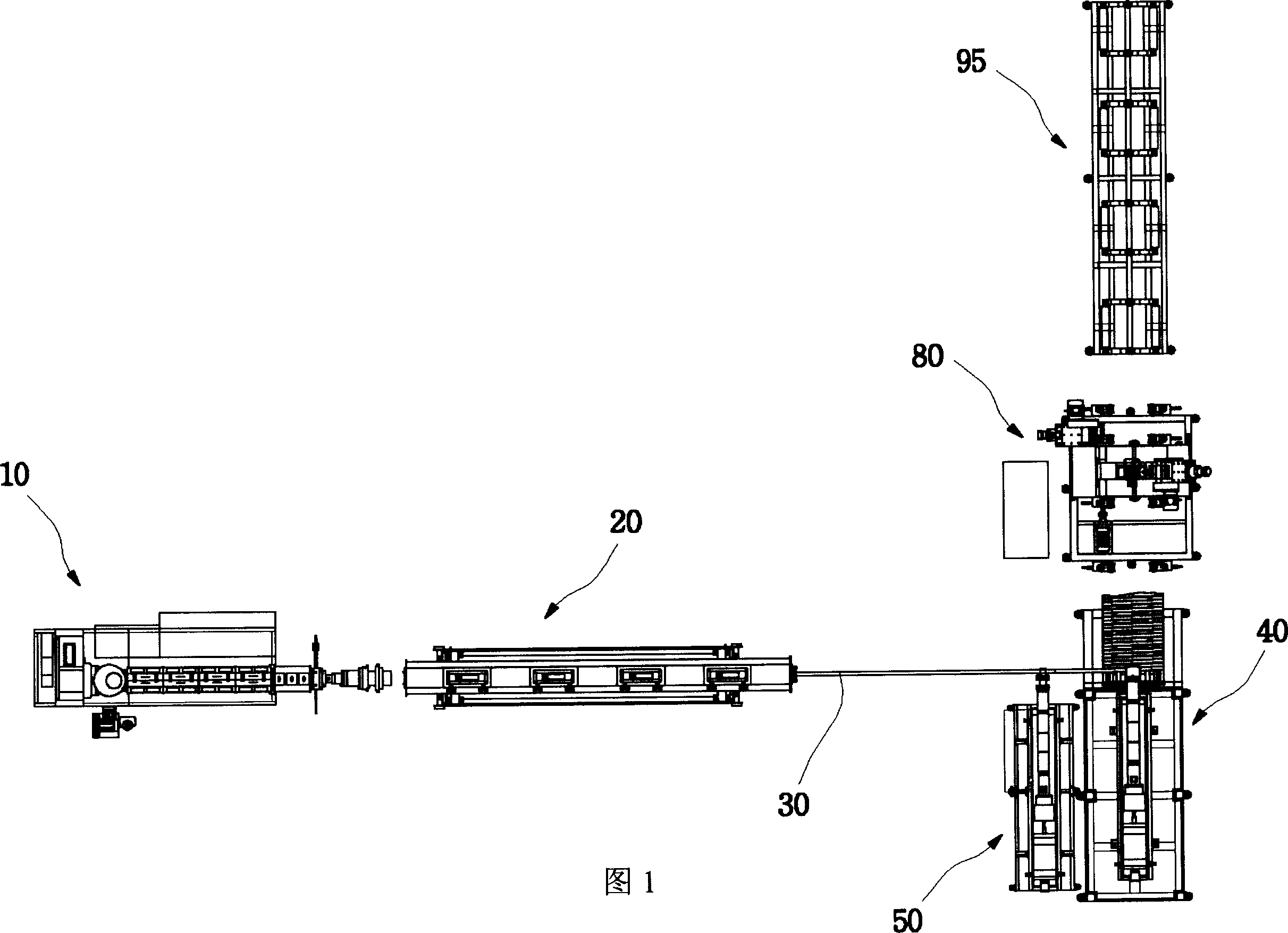
[0081] (1) Shape extrusion process

[0082] Through a pair of screws 11, the resin is melted and mixed to extrude a profile 30 with one or more central holes 31 inside.

[0083] During the above-mentioned extrusion process of the outer shape 30 , a reinforcing material such as the reinforcing duct 12 may be inserted inside the outer shape 30 .

[0084] (2) Cooling process

[0085] The extruded profile 30 is transferred to a cooling device 20 where it is cooled by a refrigerant or cold water.

[0086] At this time, the cooling device 20 is preferably maintained in a vacuum state.

[0087] (3) Shape transfer process

[0088] The cooled profile 30 is conveyed in a spiral to a hoist 41 provided on a duct forming device 40 .

[0089] (4) Inner wall covering process

[0090] The nozzle 51 of the inner wall covering extrusion device 50 covers the inner wall of the outer shape 30 with mainly yellow colored resin to form the inner diameter covering portion 52 , which forms the inn...

Embodiment approach 2

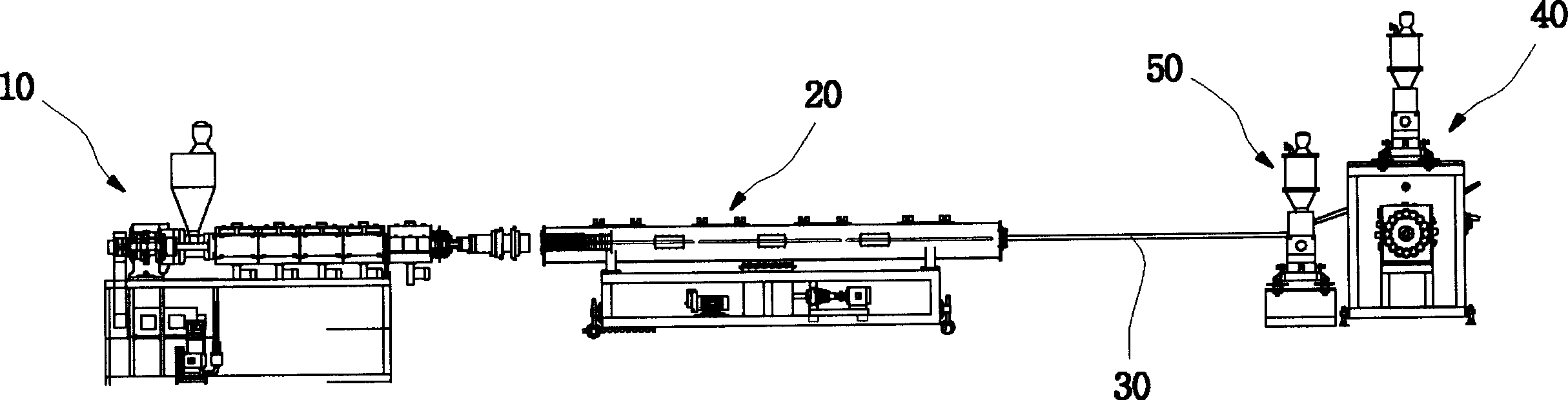
[0102] (1) Shape extrusion process

[0103] Through a pair of screws 11, the resin is melted and mixed to extrude a profile 30 with one or more central holes 31 inside.

[0104] (2) Cooling process

[0105] The extruded profile 30 is transferred to a cooling device 20 where it is cooled by a refrigerant or cold water.

[0106] At this time, the cooling device 20 is preferably maintained in a vacuum state.

[0107] (3) Shape transfer process

[0108] The cooled profile 30 is conveyed in a spiral to the hoist 41 provided on the duct forming device 40

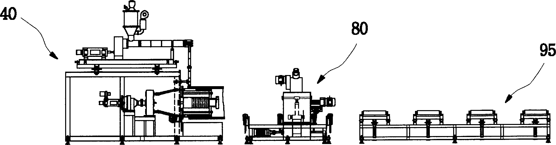
[0109] (5) hoisting process

[0110] The outer shape 30 forms the inner diameter covering part 52, and after forming the inner wall 71, when it is conveyed to the outside of the drum 42 of the winch 41 in a spiral shape, resin is supplied between the outer shapes 30 from the connection nozzle 61 connected to the extrusion device 60, and the outer shapes 30 are connected to each other to form a conduit. .

[0111] (6) Inner d...


PUM


Abstract

PURPOSE: A double-wall pipe connected spirally and a double-wall pipe forming device are provided to conveniently connect double-wall pipes without couplings by forming a double-wall screw pipe. CONSTITUTION: A double-wall pipe forming device comprises an inner circumference processing unit(100), an outer circumference processing unit(200), and a cutting unit. The inner circumference processing unit includes a feeding unit(180) installed on a table(170) in which a motor(160) is installed and an end mill rotating at a high speed by the driving force of a motor(110). The inner circumference processing unit forms a female screw portion on an inner wall. The outer circumference processing unit includes a feeding unit and an outer circumference processing cutter(250). The outer circumference processing unit forms a male screw portion on an outer wall. The cutting unit cuts one side of the male screw portion.

Description

【Technical field】 [0001] The invention relates to a threaded double-wall pipe forming device. For double-wall pipes with one or more quadrangular or circular holes inside, screws and nuts are formed at both ends of the pipe, which can easily connect the double-wall pipes to each other. Specifically, it relates to a threaded double-wall pipe forming device. The forming device integrally forms screws and nuts at both ends of the double-wall pipe to form a double-wall spiral pipe, and realizes simple connection through thread connection. 【Background technique】 [0002] In the previous double-wall pipe production process, the shape 30 with one or more quadrangular or circular holes 310 inside was extruded by the shape extrusion device 10, cooled by the cooling device 20, and sent to the hoist of the pipe forming device 40 41. At this time, the molten resin is supplied from the nozzle 61 connected to the extruding device 60 to between the outer shapes 30 to make a smooth syntheti...

Claims


Application Information

Patent Timeline
IPC IPC(8): F16L15/00B29D24/00F16L9/133F16L47/16
CPCB29C53/56B29D23/001F16L9/133F16L15/007
Inventor 金学健
Owner 金学健
Features
  • Generate Ideas
  • Intellectual Property
  • Life Sciences
  • Materials
  • Tech Scout
  • Unparalleled Data Quality
  • Higher Quality Content
  • 60% Fewer Hallucinations
Learn More