Desiccant refrigerant dehumidifier systems

A refrigeration system and drying technology, applied in refrigerators, heating and ventilation control systems, refrigeration components, etc., can solve the problem of expensive installation and achieve the effect of low energy consumption

Inactive Publication Date: 2005-12-28
MANTERS CORP
View PDF3 Cites 10 Cited by
  • Summary
  • Abstract
  • Description
  • Claims
  • Application Information

AI Technical Summary

Problems solved by technology

This type of desiccant cooling system can be designed to provide very tight and independent humidity and temperature control, but it is usually more expensive to install than traditional systems

Method used


Image

  • Desiccant refrigerant dehumidifier systems
  • Desiccant refrigerant dehumidifier systems
  • Desiccant refrigerant dehumidifier systems

Examples


Embodiment Construction

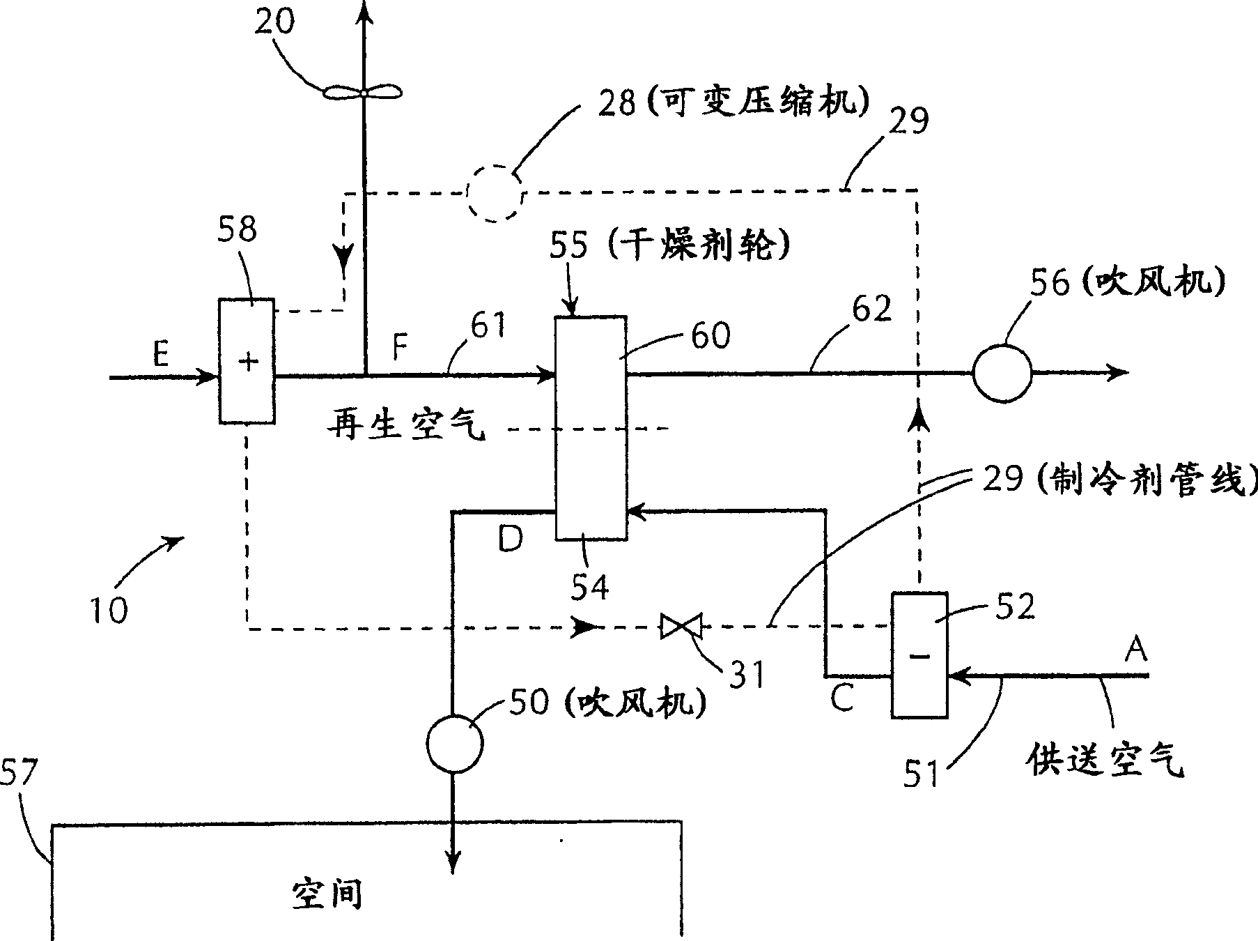
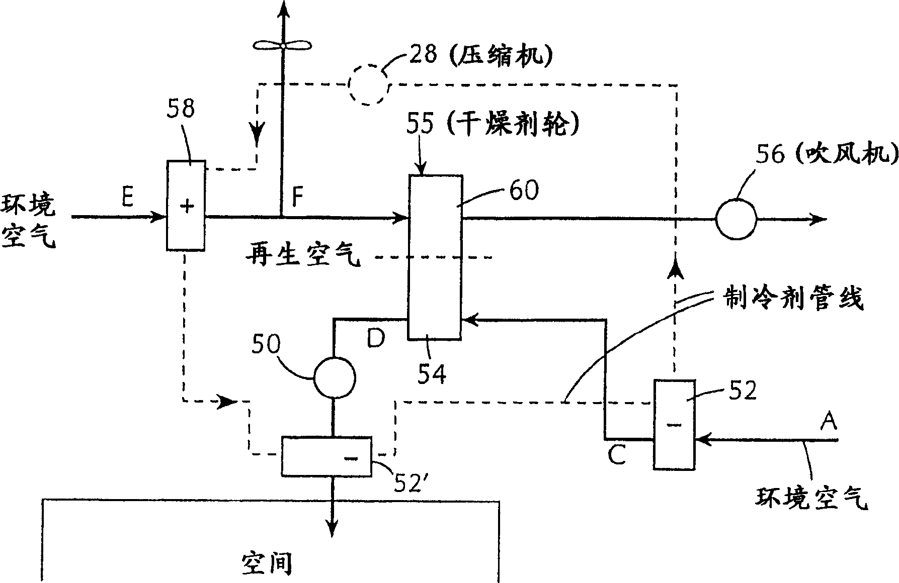
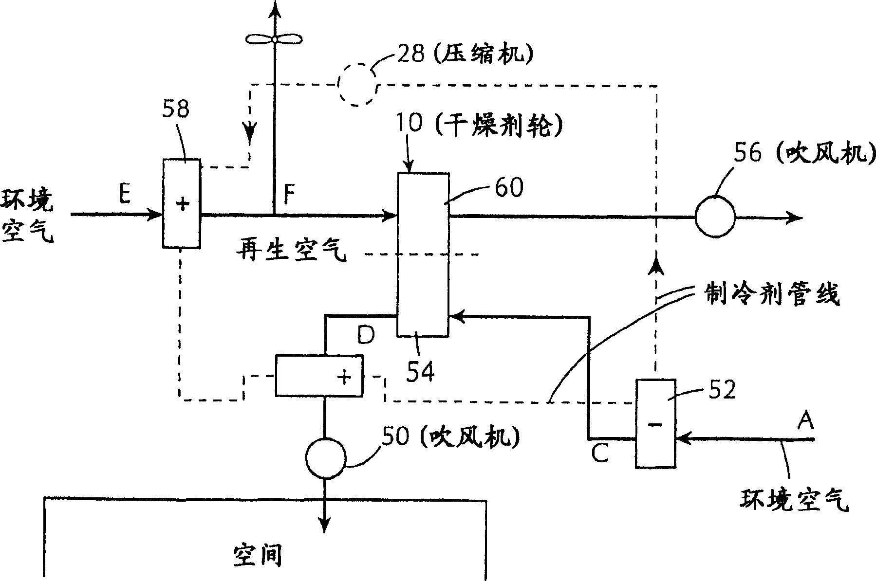
[0030] Referring now to the attached drawings in detail, see first figure 1, which shows a simplified air conditioning dehumidification system 10 according to the present invention, which uses a refrigerant cooling system and a rotating desiccant wheel dehumidification system. This system is a refinement of the system disclosed in our original application. In this case, the system takes air at any ambient state and processes it to virtually any drier, cooler humidity state with low enthalpy.

[0031] In system 10, the refrigerant cooling system comprises a refrigerant cooling circuit comprising at least one cooling or evaporator coil 52, at least one condenser for liquid / gas refrigerant carried in connecting refrigerant line 29 coil 58 and compressor 28 . In use, supply air from the atmosphere is drawn by blower 50 through ductwork 51 etc., through cooling coils 52 of the refrigeration system where it is cooled and slightly dehumidified. From there, the air passes through t...


PUM


Abstract

A method for conditioning air in an enclosed area comprising: cooling a flow of supply air using a refrigeration system comprising a variable compressor, that is, reducing the temperature of the air by passing the air through a cooling coil; causing the thus cooled A stream of feed air is passed through the rotating desiccant wheel under conditions of increasing its temperature and decreasing its moisture content, and the air thus treated is then fed into the enclosure. The desiccant wheel is regenerated by heating the regeneration air flow with the condenser coils of the refrigeration system and then passing the regeneration air flow through another portion of the rotating desiccant wheel. At least one condition of the supply air flow, the regeneration air flow, and / or the refrigeration system is sensed, and the output of the compressor is controlled in response to the sensed condition.

Description

technical field [0001] The invention relates to an air conditioner dehumidification device, in particular to an air conditioning method and a device using desiccant wheel technology. Background technique [0002] It is well known that traditional air-conditioning designs are not well suited to simultaneously handle the humidity and temperature loads in building spaces. Typically, the major source of moisture load in a building space is from the need to bring outside make-up air into the space, since this outside make-up air often has a higher moisture content than is required inside the building. In a conventional air conditioning system, the cooling capacity of the air conditioning unit is thus designed to meet the latent heat (humidity) and sensible heat (temperature) conditions at the peak temperature design conditions. A suitable dehumidification capacity is obtained when there is sufficient cooling demand. However, the moisture load on the enclosure does not directly ...

Claims


Application Information

Patent Timeline
Patent Type & Authority Applications(China)
IPC IPC(8): F24F3/14F24F5/00F24F13/22
CPCF24F3/1405F24F3/1423F24F5/001F24F2013/225F24F2203/1004F24F2203/1008F24F2203/1016F24F2203/1032F24F2203/104F24F2203/1056F24F2203/1064F24F2203/1068F24F2203/1084F24F11/30F24F2110/20F24F11/86F25B2600/0251
Inventor 保罗·A·丁纳吉凯文·H·扬
Owner MANTERS CORP
Why Eureka
Try Eureka