Electric connector and paired contact

An electrical connector and contact technology, applied in the field of electrical connectors and mating contacts, can solve the problems of electrical signal transmission delay, noise, etc., and achieve the effects of enhancing electromagnetic coupling, preventing noise, and reducing insertion loss.

Inactive Publication Date: 2005-12-28
HONDA TSUSHIN IND
View PDF0 Cites 16 Cited by
  • Summary
  • Abstract
  • Description
  • Claims
  • Application Information

AI Technical Summary

Problems solved by technology

There are various problems such as the generation of noise caused by the electrical signal due to the delay in the transmission of the electrical signal due to the difference in the line length of the circuit to the printed circuit board.

Method used


Image

  • Electric connector and paired contact
  • Electric connector and paired contact
  • Electric connector and paired contact

Examples


Embodiment Construction

[0040] The electrical connector and the mating contacts of the present invention will be described below with reference to the accompanying drawings. In order to facilitate the understanding of the present invention, parts corresponding to those in the conventional examples are assigned the same reference numerals as in the conventional examples for description.

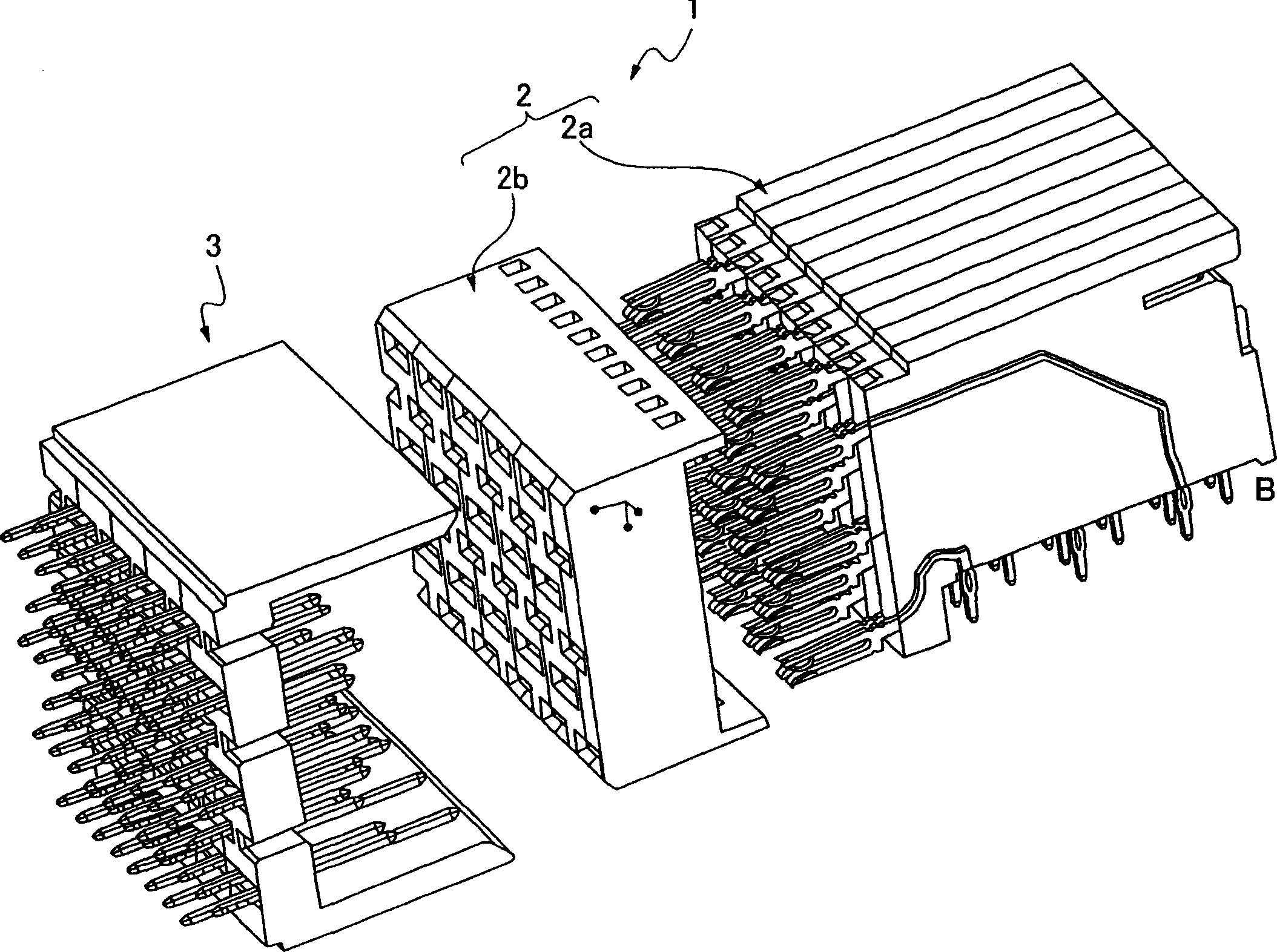
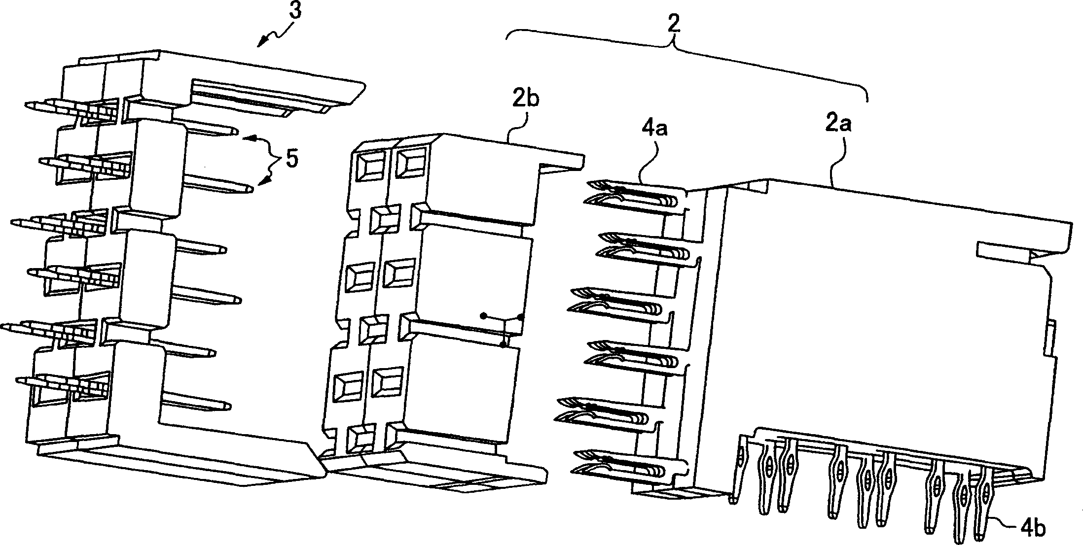
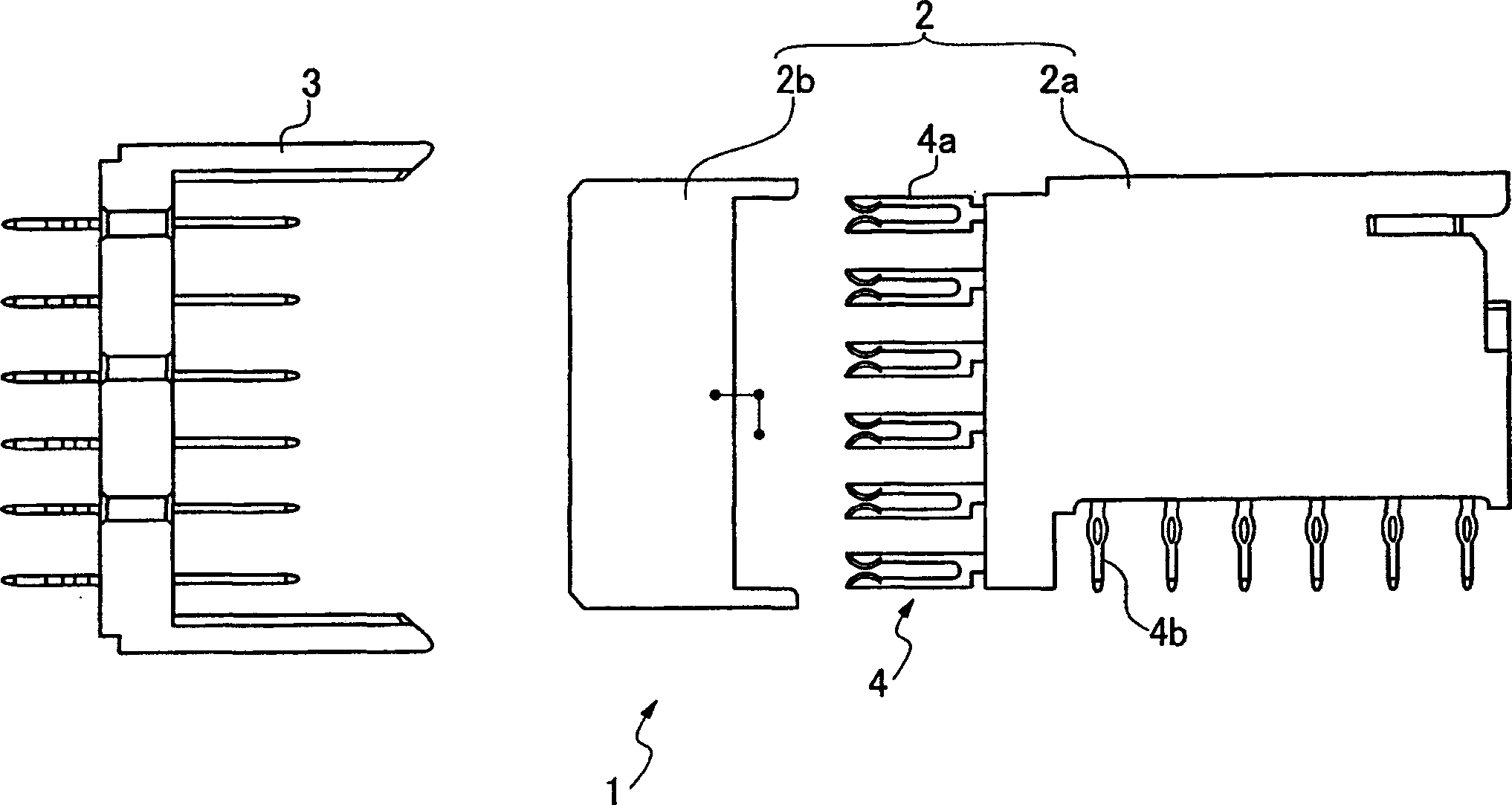
[0041] Electrical connector 1 of the present invention, such as figure 1 As shown, it includes a female package connector 2 installed on a printed circuit board so that one end of the contact is connected to the circuit and the other end of the contact becomes a female connection part, and a male connector connected to the package connector 2 is provided. Encapsulated connector 3 in the chassis.

[0042] The packaged connector 2 includes a joint housing 2b, an insulating housing 2a, and a female contact 4 that is insert-molded in the housing 2a. The female contact 4 is provided with, for example, six stages in the...


PUM


Abstract

There is provided a connector used for connection between a printed circuit board and a device or between printed circuit boards such as between a computer, a server, or a backboard-package and in particular a high-speed transmission connector for transmitting a high-frequency electric signal. The high-speed transmission connector (1) includes a plurality of signal terminals and an insulation housing having a plurality of containing holes for containing the signal terminals arranged in right-left direction in multiple stages arranged in vertical direction. In one containing hole (2c), a paired terminal (4, 4) for transmitting one electric signal is contained in such a manner that the terminals are located near to each other in the right-left direction. This increases the high-speed transmission characteristic and reduces the number of parts required.

Description

technical field [0001] The present invention relates to connectors for connecting printed substrates and devices or printed substrates such as computers, servers or backplane-packages, and mainly relates to electrical connectors and mating contacts for transmitting high-frequency electrical signals. Background technique [0002] As an existing electrical connector 11, such as Figure 10 As shown, in order to solve the noise problem, a differential transmission method is known in which a pair of mating terminals 12 constitutes a signal line and transmits a high-speed signal through the mating terminals. In this mating terminal 12, even if there is a so-called crosstalk problem in which signal energy leaks to an adjacent terminal, it can be eliminated as in-phase noise. Therefore, between the paired terminals, in order to prevent crosstalk to adjacent paired terminals, the leakage of energy from or to other signals is prevented by providing the ground terminal 13 . [0003] H...

Claims


Application Information

Patent Timeline
Patent Type & Authority Applications(China)
IPC IPC(8): H01R13/11H01R13/115
CPCH01R13/112H01R12/727H01R13/6461H01R13/6477H01R13/6587
Inventor 大西浩司松江诚彦
Owner HONDA TSUSHIN IND
Why Eureka
Try Eureka