Fluorescent lamp lighting device
A technology for lighting devices and fluorescent lamps, applied in lighting devices, light sources, electric light sources, etc., can solve problems such as high overhead, and achieve the effects of convenient sales management and convenient inventory management
- Summary
- Abstract
- Description
- Claims
- Application Information
AI Technical Summary
Problems solved by technology
Method used
Image
Examples
Embodiment approach 1
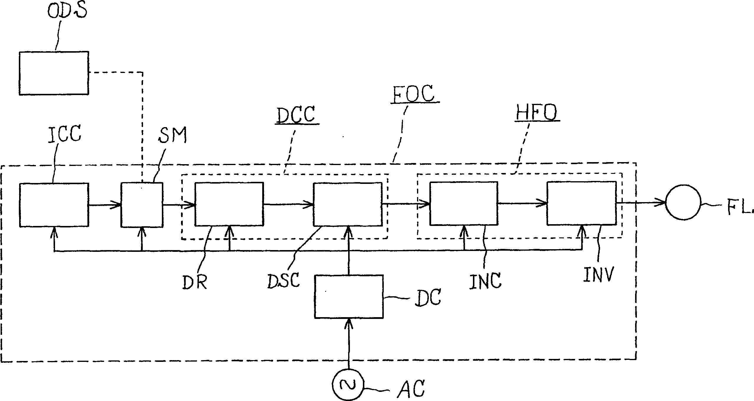
[0091] figure 1 It is a circuit block diagram showing Embodiment 1 for a fluorescent lamp lighting device embodying the present invention. In this form, the fluorescent lamp lighting device FOC has a high-frequency lighting circuit HFO, a dimming control circuit DCC, an initial illuminance correction control circuit ICC, a switching unit SM, and a direct current power supply DC. In the figure, the symbol FL is a fluorescent lamp, ODS is an external dimming signal generating circuit, and AC is a low-frequency alternating current power supply.
[0092] The high-frequency lighting circuit HFO is composed of an inverter main body INV and an inverter control circuit INC. The inverter control circuit INC is a circuit that controls the inverter main body INV as needed, and drives the inverter main body INV by supplying a frequency-controlled drive signal to the inverter main body INV, for example.
[0093] The dimming control circuit DCC generates a dimming control signal, which is...
Embodiment approach 2
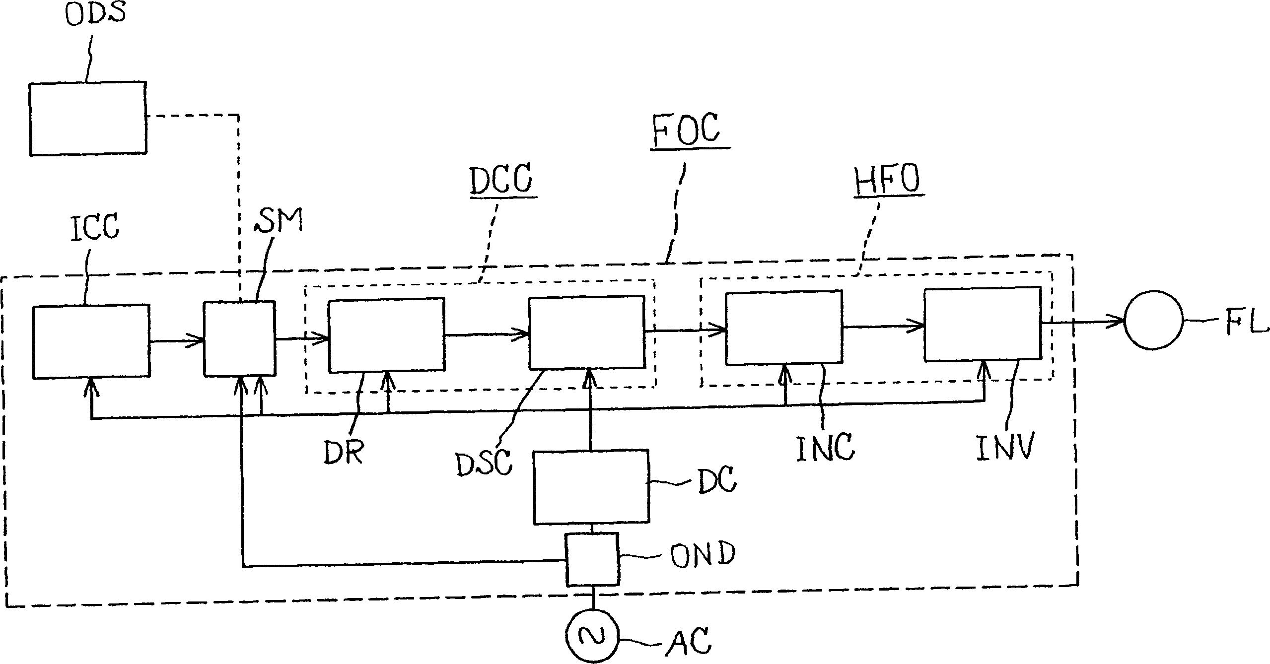
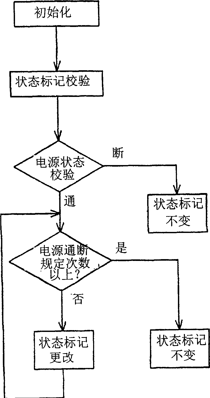
[0102] Figure 2 to Figure 4 Embodiment 2 for carrying out the fluorescent lamp lighting device of the present invention is shown, figure 2 is the block diagram of the circuit, image 3 is the flow chart of the switching unit during switching operation, Figure 4 It is a waveform diagram showing the relationship between the power supply on-off waveform and the waveform of the microcomputer power supply voltage Vdd. In this embodiment, the output of the power supply on-off regulation detection circuit OND is configured to control the switching unit SM.
[0103] The detection circuit OND and the switch unit SM are composed of a microcomputer in charge of the control of the fluorescent lamp lighting device. When the switch is completed in cooperation with each other, the image 3 The operation shown in the flowchart.
[0104] That is, flags are created and stored in the microcomputer in advance for the initial illuminance correction control lighting mode and the external cont...
Embodiment approach 3
[0110] Figure 5 and Figure 6 Embodiment 3 for carrying out the fluorescent lamp lighting device of the present invention is shown, Figure 5 is a flowchart of the switching operation of the switching unit, Figure 6It is a waveform diagram showing the relationship between the power supply on-off waveform and the power supply voltage Vdd of the microcomputer. The difference between this mode and mode 2 is: structurally, the fluorescent lamp lighting device can change the lighting mode when there is no load. Only the parts different from the mode 2 will be described below.
[0111] That is, after initialization and status verification, verify the presence or absence of load. If the fluorescent lamp lighting device is in a load state, the state flag is changed so that switching of the lighting mode is not performed. If it is a no-load state, it is judged whether the number of on-off times of the next low-frequency alternating current power source AC is more than a predeter...
PUM
 Abstract
Description
Claims
Application Information
 - R&D
- Intellectual Property
- Life Sciences
- Materials
- Tech Scout
- Unparalleled Data Quality
- Higher Quality Content
- 60% Fewer Hallucinations
Browse by: Latest US Patents, China's latest patents, Technical Efficacy Thesaurus, Application Domain, Technology Topic, Popular Technical Reports.
© 2025 PatSnap. All rights reserved.Legal|Privacy policy|Modern Slavery Act Transparency Statement|Sitemap|About US| Contact US: help@patsnap.com


