Eureka AIR delivers breakthrough ideas for toughest innovation challenges, trusted by R&D personnel around the world.

Optimized method of controlling yaw for rotary-wing aircraft, and a system for implementing it

A rotorcraft and yaw control technology, applied in control/adjustment systems, aircraft, rotorcraft, etc., can solve problems such as crosswind control restrictions, uncomfortable driving positions, and static mode offsets

Inactive Publication Date: 2006-01-18
EUROCOPTER
View PDF0 Cites 13 Cited by
  • Summary
  • Abstract
  • Description
  • Claims
  • Application Information

AI Technical Summary

Problems solved by technology

[0025] The trade-offs used in such structures usually do not provide the best optimization for all of the above constraints, and they usually increase the constraints on the operation
If the cruise chart is optimized, it will statically offset when hovering, resulting in an uncomfortable riding position (foot offset), which will limit the crosswind control from the side of the static offset of the foot
If one wishes to gain control margin (able to compensate for crosswinds) by increasing the range of control offered by the pedals, one quickly runs into the problem of driver pump effect associated with too high sensitivity

Method used


Image

  • Optimized method of controlling yaw for rotary-wing aircraft, and a system for implementing it
  • Optimized method of controlling yaw for rotary-wing aircraft, and a system for implementing it
  • Optimized method of controlling yaw for rotary-wing aircraft, and a system for implementing it

Examples


Embodiment Construction

[0046] According to one aspect of the invention, the collective pitch and yaw maps are optimized by imposing a varying bias control thereon which is a function of flight type and pilot control position.

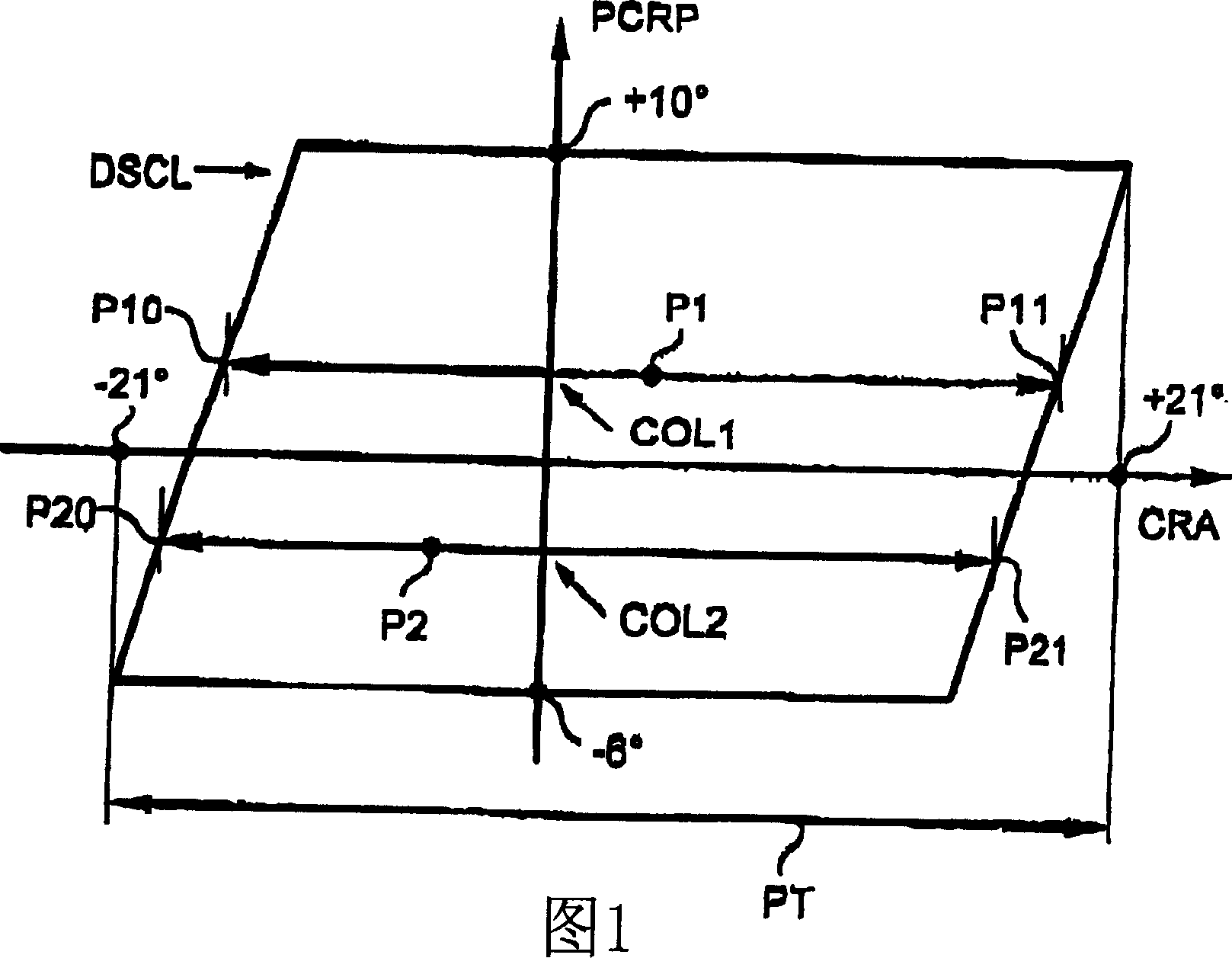
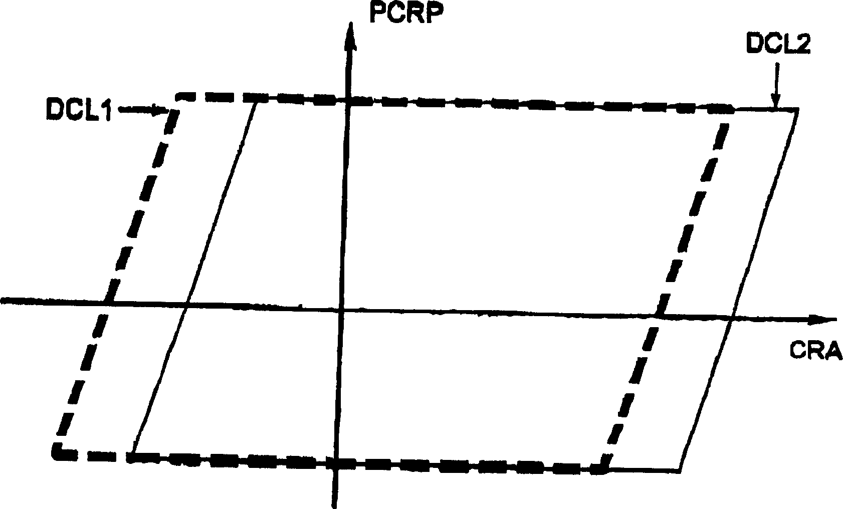
[0047] Referring to Figures 1, 2, 7 and 8, the axis of abscissa represents the magnitude of the helicopter tail rotor controlling CRA, and the axis of ordinate represents the magnitude of the main rotor collective pitch PCRP.

[0048] In the graph of FIG. 1 , the tail rotor control range P1 available to the pilot (and flight control system) for a particular collective position COL1 extends between a minimum control position P10 and a maximum control position P11 . In another collective position COL2, the tail rotor control range accessible to the pilot is a range P2 extending between a minimum control position P20 and a maximum control position P21. The switchover from P1 to P2 due to the collective pitch change from COL1 to COL2 is along the hypotenuse of the parallelogram. ...


PUM


Abstract

The invention relates to a method of controlling the blade propeller pitch of the tail rotor of a rotorcraft. The method comprises the following steps: a) a main control (18) of a blade propeller pitch of the tail rotor is produced as the function of the control element (4b) to control the blade propeller pitch of the tail rotor and operated by the pilot of the aircraft. b) A collective pitch and yaw decoupling control (16) is produced as the function of the rotor collective pitch. c) A deviation control (17) is produced and then is changed as the function of the flight velocity of the aircraft and the function of the position of the control element (4b). The deviation control is added to the decoupling control and the main control by a summing device (111) to get a collective control (10), thereby controlling the blade propeller pitch of the tail rotor.

Description

technical field [0001] The invention relates to an optimization method for yaw control of a rotorcraft and a device for implementing the method. [0002] The technical field of the invention is that of rotorcraft design. [0003] The invention more particularly relates to an optimized method for controlling the yaw of a helicopter having a main rotor and a rear rotor or tail rotor by varying the collective pitch of the tail rotor blades. Background technique [0004] Helicopter lift is provided by the main rotor through its collective pitch position. In this application, unless otherwise specified, the term "collective pitch" refers to the collective pitch of the main rotor blades. [0005] In collective pitch control the collective pitch of the main rotor blades is measured; this control is caused by a command exerted by the pilot on the collective pitch control element, but this command can also be performed by an autopilot type device as a function of other parameters ...

Claims


Application Information

Patent Timeline
Patent Type & Authority Applications(China)
IPC IPC(8): B64C27/54B64C27/78G05D1/08
CPCG05D1/0858B64C27/78
Inventor J·贝莱拉
Owner EUROCOPTER
Why Eureka
Eureka Blog
Learn More