Accumulator and its preparing method
A technology for accumulators and battery shells, which is applied in secondary battery manufacturing, electrode manufacturing, active material electrodes, etc., can solve the problems of complex mesh structure and complex battery plate manufacturing method, and achieves simple preparation method and good fast charge-discharge performance. , the effect of low internal resistance
- Summary
- Abstract
- Description
- Claims
- Application Information
AI Technical Summary
Problems solved by technology
Method used
Image
Examples
preparation example Construction
[0041] In the preparation method of storage battery of the present invention, the preparation of positive and negative plates comprises the following steps:
[0042] (1) Coating active material on both sides of positive and negative plate metal substrates, drying;
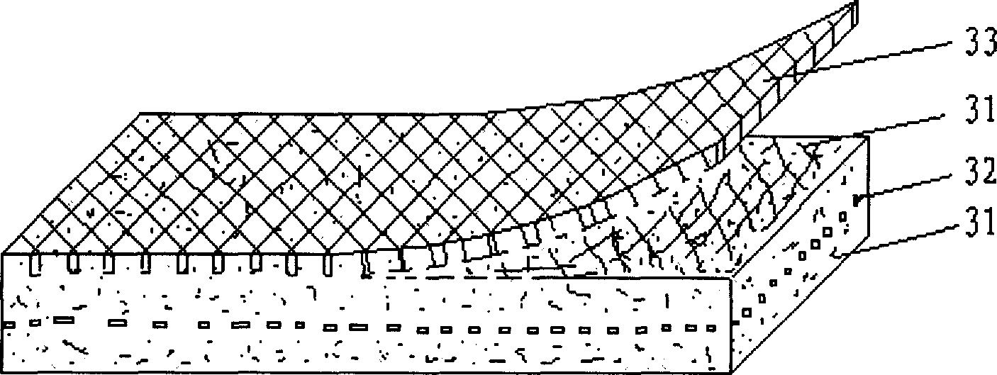
[0043] (2) embedding the metal mesh on one side of at least one of the positive plate or negative plate obtained by step (1);
[0044] (3) Rolling and cutting the polar plate.
[0045] Wherein, the drying conditions may be drying in an oven or a vertical dryer, and the temperature is preferably 80-140°C, more preferably 100-120°C. Embedding the metal mesh into the side of the plate can be achieved by rolling.
Embodiment 1
[0048] Preparation of the positive electrode: Spherical nickel hydroxide, cobaltous oxide, a small amount of additives and binders, and water are stirred in a certain proportion to form a paste slurry, and the slurry is filled with a surface density of 430g / m 2 1. One side is welded in the foamed nickel with nickel strip-shaped drainage terminal, and then after drying, a metal mesh with the same size as the side area of the foamed nickel is rolled on one side of the pole piece. The thickness of the metal mesh is 0.25mm, and the aperture is It is 2.0×4.0mm, and the mesh rate is about 88% nickel cable-stayed mesh. Finally, a positive electrode plate with a size of 85mm×40mm×0.65mm was obtained by rolling and cutting, wherein the embedded depth of the metal mesh was 0.20mm.
[0049]Preparation of negative electrode: Weigh alloy powder, binder, and additives, mix them in a certain proportion, stir them into a paste, coat them on a punched nickel-plated steel strip, dry, roll, an...
Embodiment 2
[0052] Preparation of the positive electrode: except that there is no rolled metal mesh, the rest is the same as the positive electrode plate in Example 1.
[0053] Preparation of the negative electrode: Weigh the alloy powder, binder, and additives, mix them in a certain proportion, stir them into a paste, coat them on the perforated nickel-plated steel strip, dry them, and roll the metal mesh on the negative electrode side. Adopt the nickel cable-stayed mesh identical with embodiment one specification. The size of the nickel cable-stayed mesh used is the same as the side area of the perforated nickel-plated steel strip of the negative electrode, and it is cut into a negative plate with a size of 115mm×40.7mm×0.34mm, wherein the embedded depth of the metal mesh is 0.15mm.
[0054] Battery assembly: the same as in Embodiment 1.
PUM
| Property | Measurement | Unit |
|---|---|---|
| depth | aaaaa | aaaaa |
| pore size | aaaaa | aaaaa |
| thickness | aaaaa | aaaaa |
Abstract
Description
Claims
Application Information
 - R&D
- Intellectual Property
- Life Sciences
- Materials
- Tech Scout
- Unparalleled Data Quality
- Higher Quality Content
- 60% Fewer Hallucinations
Browse by: Latest US Patents, China's latest patents, Technical Efficacy Thesaurus, Application Domain, Technology Topic, Popular Technical Reports.
© 2025 PatSnap. All rights reserved.Legal|Privacy policy|Modern Slavery Act Transparency Statement|Sitemap|About US| Contact US: help@patsnap.com


