Revolving plate for a sliver depositing device

A technology of fiber slivers and turntables, which is applied in fiber processing, transportation and packaging, textiles and papermaking, etc., and can solve the problems of fiber sliver accidental drafting, deterioration of fiber parallelism, and damage to fiber sliver quality, etc.

Inactive Publication Date: 2006-01-25
RIETER INGOLSTADT SPINNEREI
View PDF1 Cites 3 Cited by
  • Summary
  • Abstract
  • Description
  • Claims
  • Application Information

AI Technical Summary

Problems solved by technology

For example, particulate deposits can cause the fiber sliver to be drawn unintentionally, or to deteriorate the parallelism of the fibers
[0005] Another disadvantage is that when using said turntable during production, high longit

Method used


Image

  • Revolving plate for a sliver depositing device
  • Revolving plate for a sliver depositing device
  • Revolving plate for a sliver depositing device

Examples


Embodiment Construction

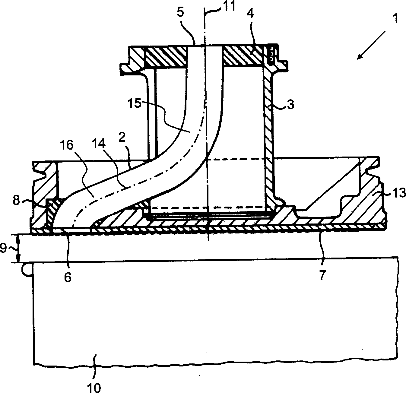
[0045] according to figure 1 , the known turntable 1 includes a disc body 13, a disc frame 3 and a centerline 14 space curve fiber strip pipe 2. The upper end of the fiber strip pipeline 2 utilizes casting material 4 to be fixed on the disc frame 3, and the lower end utilizes 8 casting materials to be fixed on the disc body 13. The disc body 13 has a pressing plate surface 7 at its lower end. During operation, the turntable 1 rotates around its axis 11 . The method of rotating disk support and rotation is not shown among the figure.

[0046] The fiber sliver enters the fiber sliver pipeline 2 parallel to the rotating shaft 11 within the scope of the input port 5, then turns around and leaves the fiber sliver pipeline through the output port 6 and enters the can 10 for stacking. The output port 6 is on the pressure plate surface 7 on the plane. The distance 9 between the pressing plate 7 and the can 10 will be chosen so small that it is impossible for the stacked fiber stra...


PUM


Abstract

The present invention provides a revolving plate for a sliver depositing device of a sliver-producing or sliver-processing spinning preparation machine is suggested that is designed for depositing sliver supplied in a running manner into a container (10), which revolving plate (1) has a press surface (7) arranged vertically to its axis of rotation (11) for pressing the deposited sliver into the container (10) and has a sliver passage (2) with a helical spatial curve , whereas the entrance opening (5) of the sliver passage (2) is arranged in such a manner that the supplied sliver enters into the sliver passage (2) parallel to the axis of rotation (11) of the revolving plate (1) and without bends, and whereas the exit opening (6) of the sliver passage (2) is in the plane of the press surface (7). The revolving plate in accordance with the invention is distinguished in that the sliver passage (2) has such a shape at least on a predominant part of its length that at a given ratio between the supply speed of the sliver and the speed of the revolving plate (1) substantially no force acting on the sliver to be deposited and tangential to the axis of rotation (11) of the revolving plate (1) occurs along the sliver passage (2) in order to reduce in this manner the friction of the sliver on the inner wall of the sliver passage in order to prevent the accumulation and collecting of particles on the inner wall of the sliver passage that loosened out of the sliver. A corresponding method for depositing a sliver supplied in a running manner into a container is also suggested.

Description

technical field [0001] The invention relates to a turntable for a fiber sliver stacking device for sliver making or processing spinning preparation machines according to the general concept of claim 1, and to a stacking of continuously transported fiber sliver according to the general concept of claim 18 A method in a can. Background technique [0002] According to German patent DE 41 31 134, the known rotary table has a spatially curved fiber sliver duct, and the fiber sliver duct is formed by a pipe joint, which is connected by two circular arcs which are diverted from each other. This has the disadvantage that sometimes the particles detached from the fiber sliver deposit on the inner wall of the fiber sliver duct. [0003] The tendency of the particles to aggregate is to gradually grow to a certain size during the production of the sliver pack and then to detach from the inner wall of the pipe as a compact particle agglomerate. This detachment mostly occurs when changi...

Claims


Application Information

Patent Timeline
IPC IPC(8): D01G27/00B65H54/80
CPCB65H54/80B65H2701/31
Inventor M·施特罗贝尔CH·谢里夫G·施魏格尔
Owner RIETER INGOLSTADT SPINNEREI
Why Eureka
Try Eureka