

Terminal for monitoring urban street light circuit
A technology for monitoring terminals and street lamps, which can be applied to the layout of electric lamp circuits, sustainable buildings, instruments, etc., and can solve the problems that street lamps are difficult to realize remote monitoring.
- Summary
- Abstract
- Description
- Claims
- Application Information
AI Technical Summary
Problems solved by technology
Method used
Image

Examples
specific Embodiment approach 1
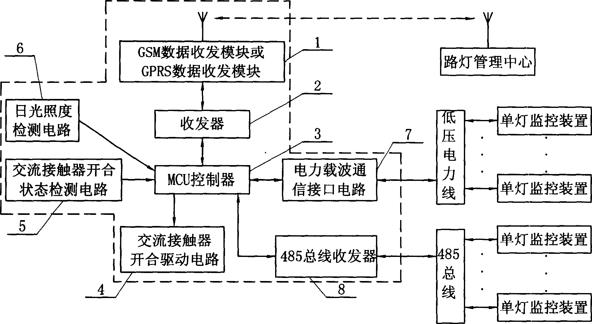
[0005] Specific implementation mode one: the following combination figure 1 This embodiment will be specifically described. This embodiment consists of a GSM data transceiver module or a GPRS data transceiver module 1, a transceiver 2, an MCU controller 3, an AC contactor opening and closing drive circuit 4, an AC contactor opening and closing state detection circuit 5, and a sunlight illumination detection circuit 6. One communication end of the GSM data transceiver module or GPRS data transceiver module 1 is connected to one end of the transceiver 2, the other end of the transceiver 2 is connected to a communication terminal of the MCU controller 3, and an input end of the MCU controller 3 is connected to the sunlight detection circuit 6, the other input end of the MCU controller 3 is connected to the output end of the AC contactor opening and closing state detection circuit 5, and the output end of the MCU controller 3 is connected to the input end of the AC contactor openi...
specific Embodiment approach 2
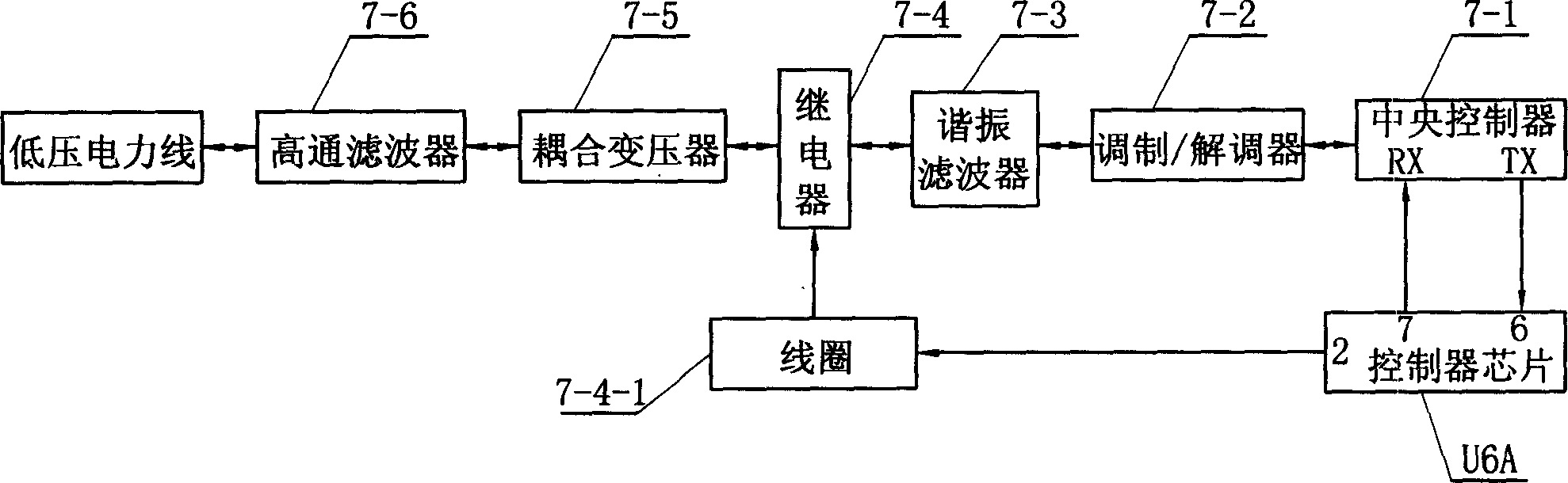
[0006] Specific implementation mode two: the following combination figure 1 This embodiment will be specifically described. The difference between this embodiment and Embodiment 1 is that it also includes a power carrier communication interface circuit 7 , one communication end of the power carrier communication interface circuit 7 is connected to the other communication end of the MCU controller 3 . In this way, the terminal of the present invention can communicate with the single-lamp monitoring device installed on each street lamp through the low-voltage power line that supplies power to each street lamp, so as to realize real single-lamp control and fault detection, and accurately calculate the lighting rate parameters , realizing the automatic control of multi-period and multi-scenario (street lights on or off interval change and brightness change) mode according to the time control strategy table. Other composition and connection modes are the same as those in Embodimen...
specific Embodiment approach 3
[0007] Specific implementation mode three: the following combination figure 1 This embodiment will be specifically described. The difference between this embodiment and the first embodiment is that it also includes a 485 bus transceiver 8 , and one end of the 485 bus transceiver 8 is connected to another communication end of the MCU controller 3 . In this way, on the premise that each street lamp is connected to the 485 bus, the terminal of the present invention can communicate with the single lamp monitoring device through the 485 bus. Other composition and connection modes are the same as those in Embodiment 1.
PUM
 Abstract
Description
Claims
Application Information