Deinking device

A deinking machine and ink collection technology, which is applied in the field of papermaking machinery, can solve problems such as increased operating costs, complex structure, and difficult maintenance of operating parts, and achieve the effect of saving use costs and simple structure

Inactive Publication Date: 2006-02-01
李风宁
View PDF0 Cites 8 Cited by
  • Summary
  • Abstract
  • Description
  • Claims
  • Application Information

AI Technical Summary

Problems solved by technology

[0004] The disadvantages of the above-mentioned flotation cell are: 1. Because the flotation cell is a large airtight container with complex structure and high failure r

Method used


Image

  • Deinking device
  • Deinking device
  • Deinking device

Examples


Embodiment Construction

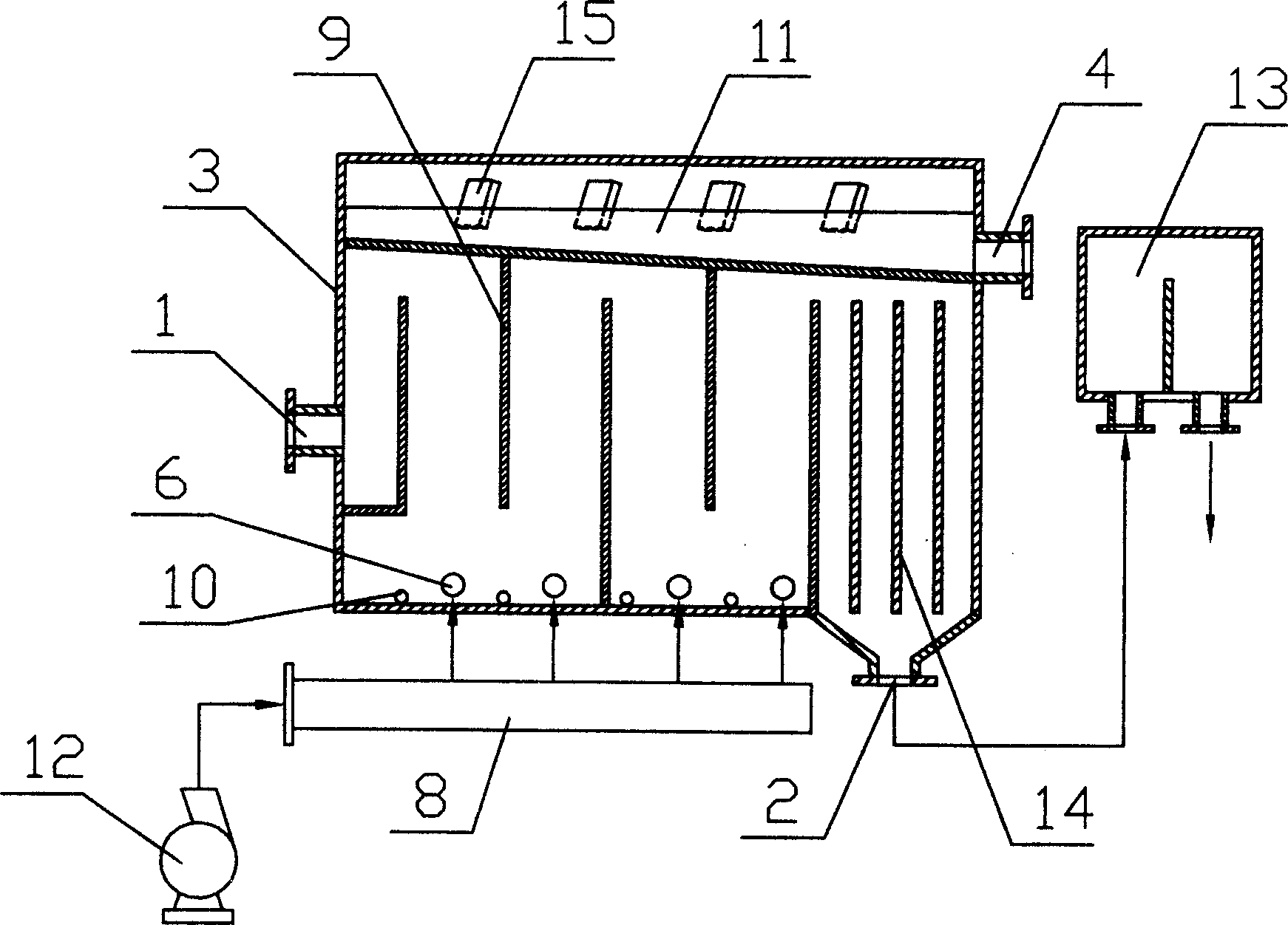
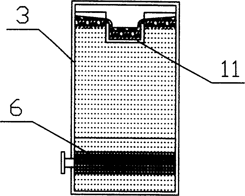
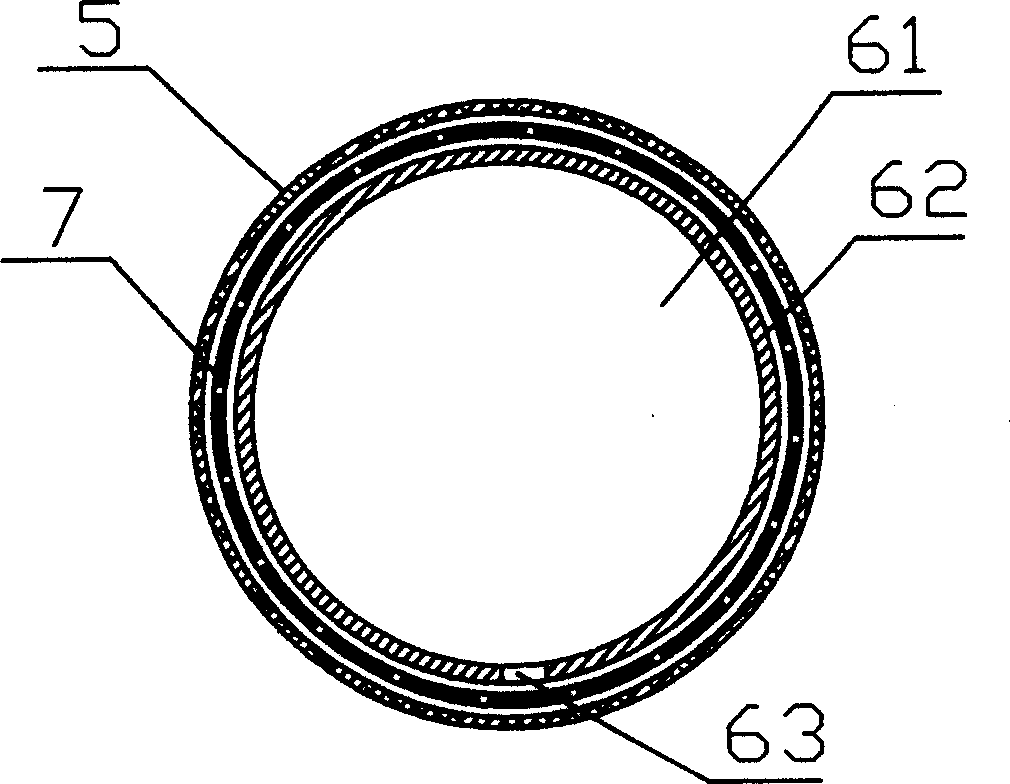
[0021] like figure 1 , figure 2 , image 3 , Figure 4 As shown, a deinking machine includes a deinking machine housing 3, a liquid inlet 1 arranged on one side of the deinking machine housing 3 and a liquid outlet 2 arranged on the other side of the bottom of the deinking machine housing 3, The ink collecting device on the upper part of the cavity of the deinking machine housing 3 and the slag outlet 4 connected to the ink collecting device. The bottom of the cavity of the deinking machine housing 3 is equipped with a The microporous aeration device 6 that sends the flotation air bubbles, and the air inlet pipe 8 connected to the microporous aeration device 6, the air inlet pipe 8 is fed by the blower 12, and the liquid outlet 2 of the air inlet pipe 8 is connected to the liquid level tank 13 , The function of the liquid level box 13 is to maintain a certain liquid level of the deinking machine housing 3, and only the waste residue enters the ink collecting device and is...


PUM


Abstract

A deinking machine for treating the paper-making sewage is composed of a casing with liquid inlet and outlet, an ink collector with dregs outlet, and a millipore aerating unit with air inlet tube for blowing the air bubbles in the sewage by high-pressure air. When the air bubbles are diffused in the sewage, the ink in the sewage is adsorbed by them. When said air bubbles are broken on the surface of sewage, the ink is collected by the ink collector and then discharged via dregs outlet.

Description

technical field [0001] The invention relates to a papermaking machine, in particular to a machine for deinking waste paper pulp or papermaking wastewater. Background technique [0002] In the waste paper treatment technology, the recovered waste paper is crushed, decomposed, and added with chemicals to separate the printing ink and fibers in the waste paper to form a non-deinked pulp suspension, that is, mortar. Then the waste paper pulp is deinked by flotation process to improve the whiteness of the waste paper pulp. As we all know, air bubbles play an irreplaceable role in flotation, and the number, size and stability of the bubbles all affect the flotation effect. In order to allow more ink particles to be adsorbed onto the air bubbles, the diameter distribution of the air bubbles should be broad-spectrum to capture ink particles of different sizes. [0003] as attached Figure 5 The flotation cell shown is a kind of flotation cell jointly developed by Black Clawson Com...

Claims


Application Information

Patent Timeline
IPC IPC(8): D21C9/08
CPCY02W30/64
Inventor 李风宁
Owner 李风宁
Why Eureka
Try Eureka