
Real time centralized monitoring device for channels in radio frequency in time division duplexing system

A technology of time division duplex system and radio frequency channel, applied in transmitter monitoring, transmission monitoring, transmission system and other directions, can solve problems such as poor real-time performance, simplify bus design, reduce complexity and failure rate, and improve reliability and resistance. disturbing effects

Inactive Publication Date: 2006-02-01
ZTE CORP
View PDF1 Cites 14 Cited by
  • Summary
  • Abstract
  • Description
  • Claims
  • Application Information

AI Technical Summary

Problems solved by technology

It will lead to poor real-time performance. In some emergency failures, such as excessive RF output power, it is necessary to immediately turn off the power of the entire RF channel to ensure safety. If you upload data and wait for commands at this time, the 10ms delay will also cause serious consequences.

Method used


Image

  • Real time centralized monitoring device for channels in radio frequency in time division duplexing system
  • Real time centralized monitoring device for channels in radio frequency in time division duplexing system

Examples


Embodiment Construction

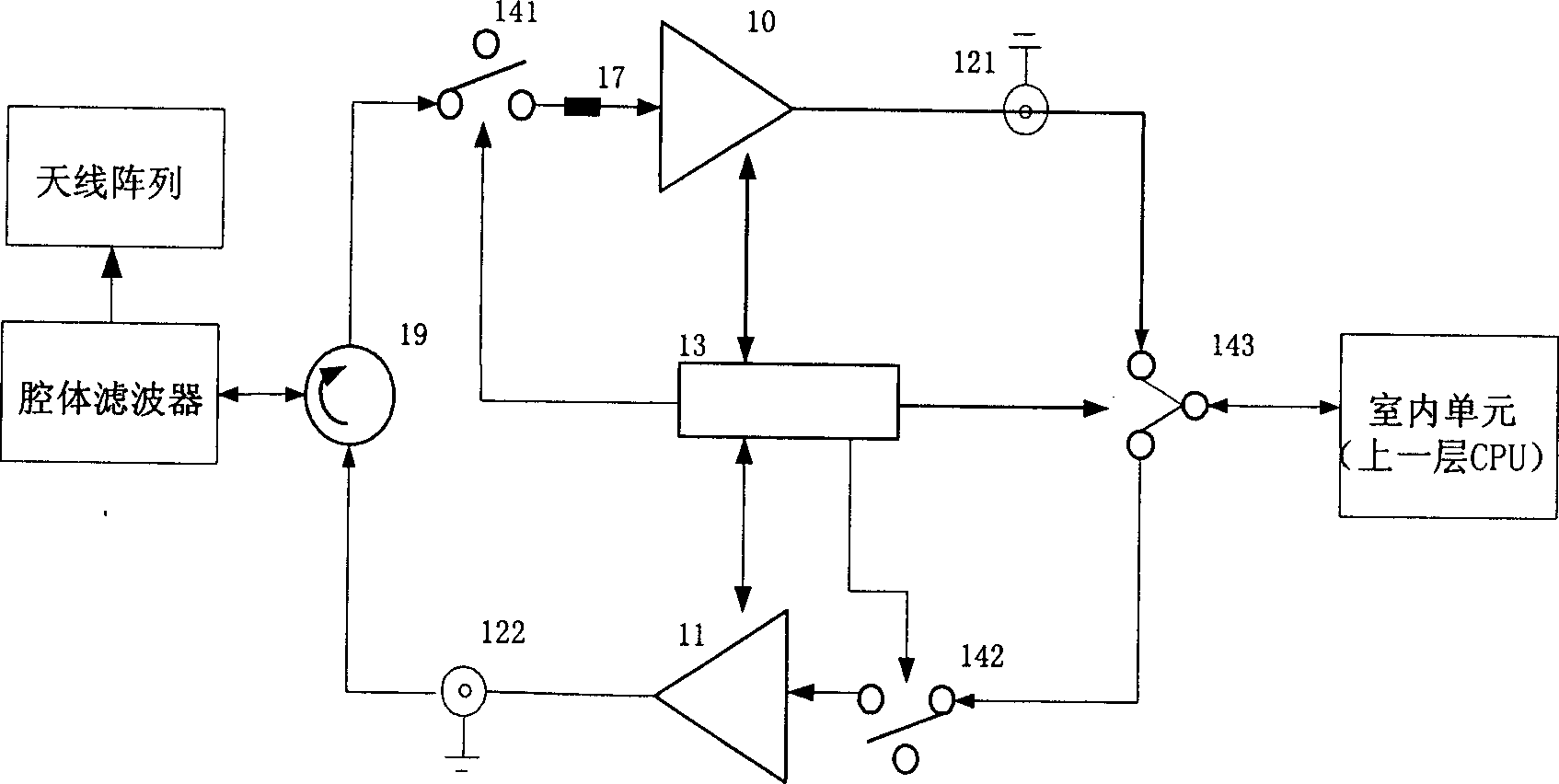
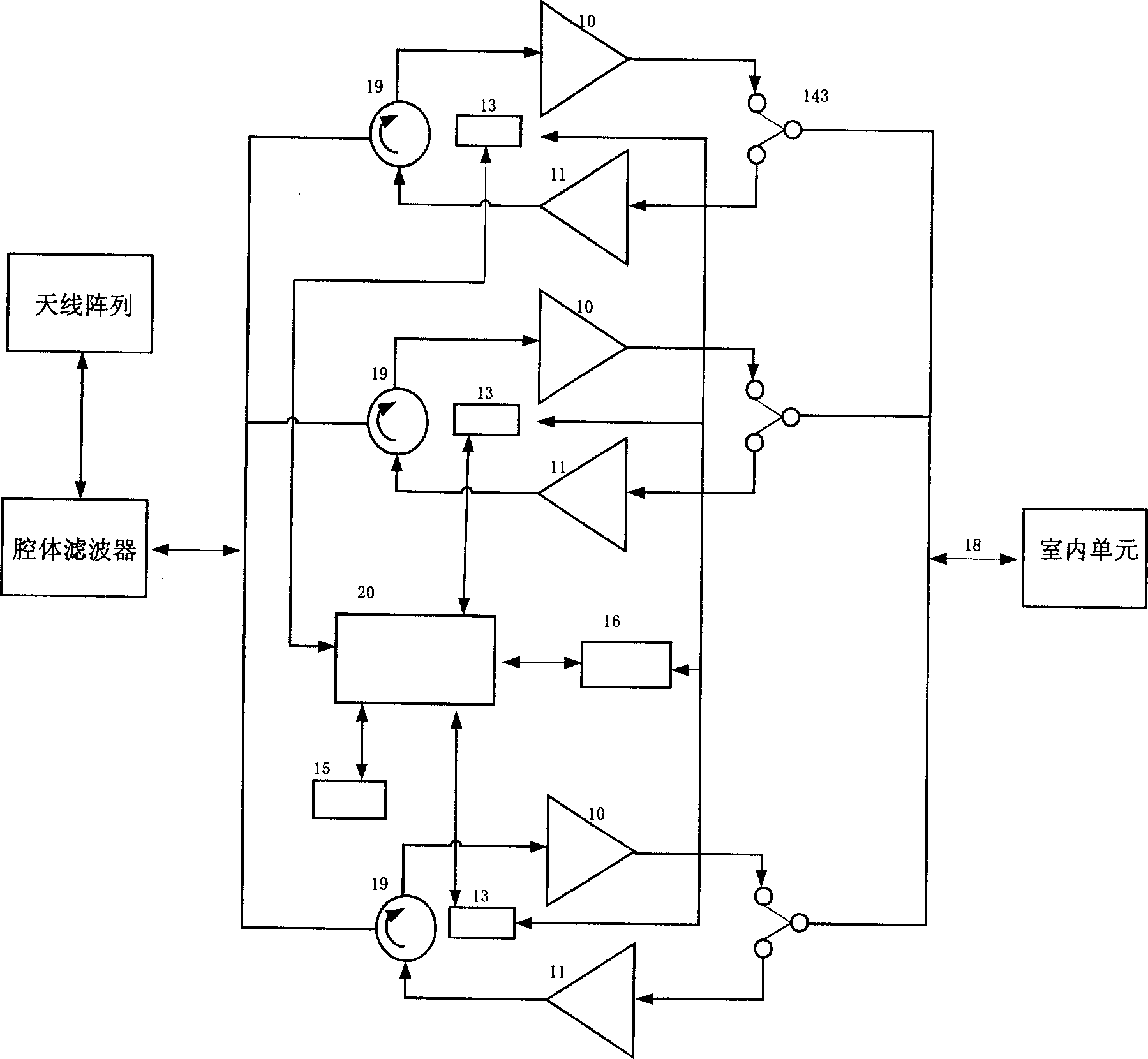
[0025] like figure 1 As shown, a specific channel in this embodiment mainly includes a low noise amplifier unit 10, an amplifier circuit 11, two temperature compensation circuits 121, 122, a radio frequency channel protection detection and control circuit 13, and three radio frequency switch circuits 141, 142, 143, current sensor 17, loop filter 19. The loop filter 19 on the monitoring device is connected to the antenna array through the cavity filter, the third radio frequency switch 143 on the device is connected to the indoor unit, the first radio frequency switch 141, the current sensor 17, the low noise amplifier unit 10 in the receiving direction The first temperature compensation circuit 121 is connected in sequence; the second radio frequency switch 142 , the amplifier circuit 11 , and the second temperature compensation circuit 122 are connected in sequence in the sending direction. The radio frequency channel protection detection and control circuit 13 is connected ...


PUM


Abstract

The monitoring device includes multiple channels in radio frequency, power supply management circuit, interface circuit and centralized setup processing module. The power supply management circuit is in use for supplying power, toggling power switch, and testing input current. The interface circuit provides interfaces of power supply, communication and radio frequency signal for all channels to connect with upper layer. The processing module includes parts: correction control unit for controlling data correction of all channel; protection control unit in use for carrying out real time calculation and process locally based on tested data in order to generate control command for protecting channels; communication unit in use for transferring notification and command to up layer system. Further, real time calibration for each channel circuit can be completed locally. Under condition of ensuring reliability, rapidity and maintainability are raised, and cost is lowered.

Description

technical field [0001] The invention relates to a monitoring device for realizing a radio frequency transceiver end of a wireless communication system, in particular to a real-time centralized monitoring device for a time division duplex (TDD) system radio frequency transceiver end. Background technique [0002] The real-time monitoring device at the RF transceiver end of the TDD system is the data acquisition, control and communication core of the RF part of the entire outdoor base station communication system. It is used in the TDD wireless communication system to perform multi-channel two-way transceiver monitoring on the wireless signals transmitted by the base stations in the system. [0003] The development of modern communication technology requires that the capacity of a single base station can be larger, so more radio frequency channels need to be added, and base stations with four channels or more have greater market potential. At the same time, the maintenance wo...

Claims


Application Information

Patent Timeline
IPC IPC(8): H04B17/00H04B17/18
Inventor 文耀彤王文焕王长明华海宁
Owner ZTE CORP
Learn More