

Optical glass
An optical glass, refractive index technology, applied in optics, optical components, instruments, etc., can solve the problems of low resistance to devitrification, difficulty in manufacturing glass preform materials, and lack of optical constants.
Inactive Publication Date: 2006-02-01
OHARA
View PDF7 Cites 29 Cited by
- Summary
- Abstract
- Description
- Claims
- Application Information
AI Technical Summary
Problems solved by technology
The glass actually disclosed in Publication 7 has an optical constant in the above-mentioned specific region, but has a defect that it is difficult to manufacture a glass preform material because of its low resistance to devitrification
In addition, due to the large amount of WO 3 or TiO 2 , so there is also the defect of low transmission coefficient in the short visible wavelength range
[0025] As described above, the high-refractive-index and low-dispersion optical glass according to early development mainly has the following problems: although its transition temperature is low, its optical constant is not in the above-mentioned specific region which is highly required in recent years; or although its optical constant is in the above-mentioned specific region, but the transition temperature (T g ) high, which makes precision molding difficult
Method used
View moreImage
Smart ImageViewing Examples

Examples
Embodiment
[0114] Embodiments of the present invention will be described below. However, needless to say, the present invention is not limited to these Examples.
[0115] Tables 1-6 show the compositions of examples of glasses according to the invention (No. 1 to No. 32) together with their refractive indices (n d ), Abbe number (ν d ) and transition temperature (T g ).
[0116] Tables 7 and 8 show the compositions of the glasses (No. A to No. H) of the comparative examples together with their refractive indices (n d ), Abbe number (ν d ) and transition temperature (T g ).
Login to View More PUM
| Property | Measurement | Unit |
|---|---|---|
| Transition temperature | aaaaa | aaaaa |
Abstract
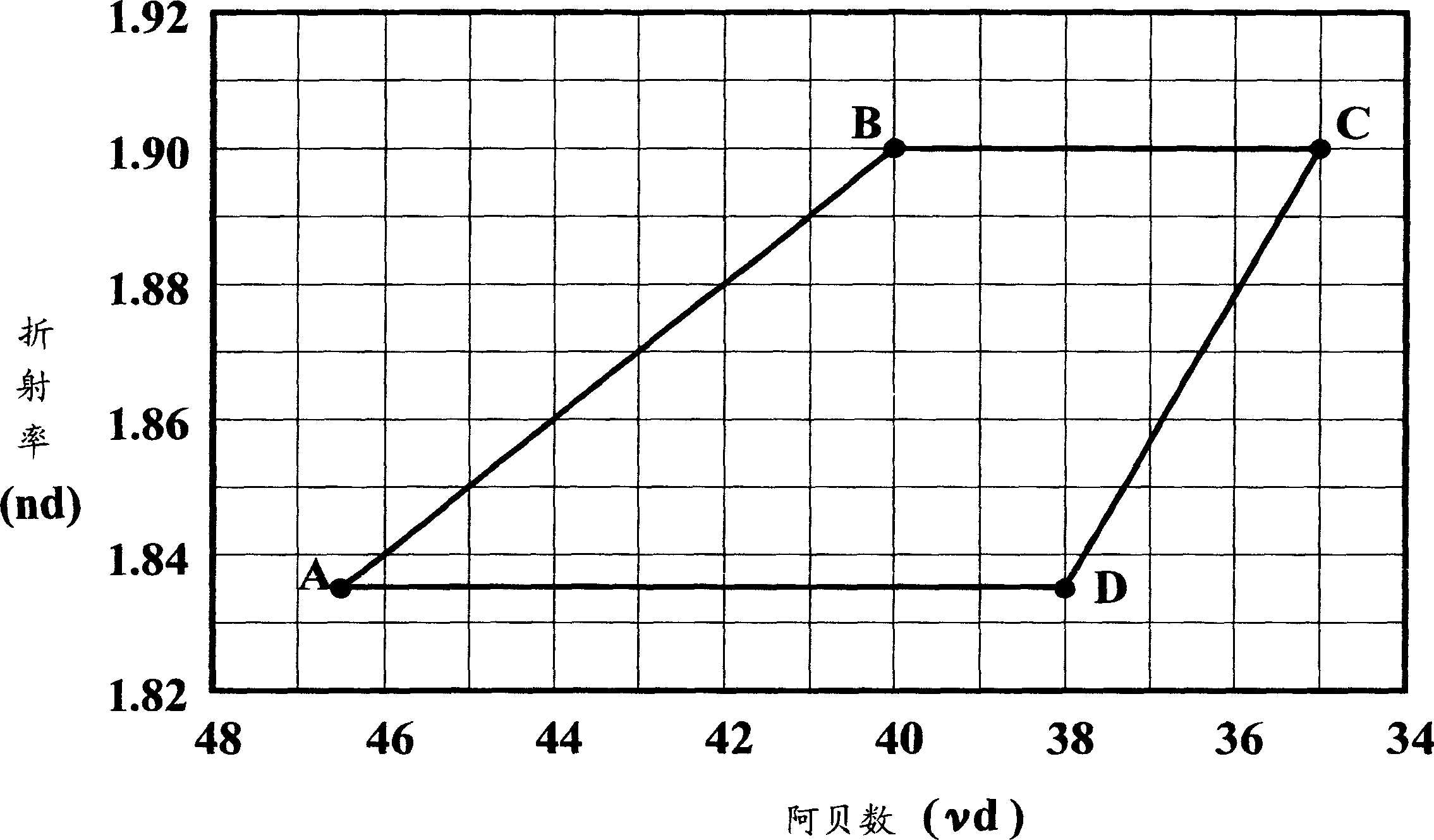
The present invention provides an optical glass having a refractive index (nd) and an Abbe number (vd) which are within an area surrounded by the straight lines which are drawn by connecting point A (nd=1.835, vd=46.5), point B (nd=1.90, vd=40.0), point C, (nd=1.90, vd=35.0) and point D (nd=1.835, vd=38.0) in a sequence of A, B, C, D and A as border lines in x-y coordinates shown in fig 1, in which X-axis is the Abbe number (vd) and Y-axis is the refractive index (nd), the area including the border line. The optical glass has low glass transition temperature (Tg), and suitable for precision mold pressing. The optical glass which has the refractive index (nd) and Abbe number (vd) within the above-described area, where the area includes the border lines, has the composition of SiO2-B2O3-La2O3-Gd2O3-Li2O-F system, the transition temperature (Tg) of 550 to 650 DEG C., and is free from lead, cadmium, thorium, Y2O3, P2O5 and TeO2.
Description
technical field [0001] The present invention relates to a glass preform material used in precision molding and an optical glass suitable for precision molding, which has a low transition point (T g ) as well as low dispersion and high refractive index. Background technique [0002] In recent years, in optical instruments that have become significantly smaller and lighter, aspheric lenses are often applied to reduce the number of lenses constituting the optical system of the optical instrument. A method of producing a lens by press-forming or precision-molding a thermosoftened glass preform material with a metal stamper having a precisely shaped surface is the mainstream of manufacturing glass aspheric lenses. [0003] Since the glass molding obtained by precision molding exists in the form of a final product such as a lens formed with little or no grinding and polishing, it is possible to manufacture lenses and the like with high productivity using precision molding. The p...
Claims
Login to View More Application Information
Patent Timeline
 IPC IPC(8): C03C3/068G02B1/02
CPCC03C3/068
Inventor上原进清水晃治增子慎弥
OwnerOHARA