
Lift gate installation drived by direct current linear motion actuator

A linear motor and driving technology, applied in the direction of electromechanical devices, electric components, elevators in buildings, etc., can solve the problems of increasing the weight of the door control system, poor contact faults, occupation, etc., to achieve easy speed control and reduce mechanical Device, create simple effects

Inactive Publication Date: 2006-02-22
戴开煌
View PDF3 Cites 5 Cited by
  • Summary
  • Abstract
  • Description
  • Claims
  • Application Information

AI Technical Summary

Problems solved by technology

It has the following obvious shortcomings: First, the torque characteristics at low speeds are not good, so the motor must be operated at higher speeds, and mechanical devices such as gears or pulleys are used to reduce the door speed.
These additional devices not only occupy the already narrow space at the top of the elevator car, increase the weight of the door control system, but also increase the failure rate and maintenance cost of mechanical moving parts
The second is that the current is large when the rotor is locked, and it is easy to burn out the motor and its additional speed control device.
The third is that the rotor of the motor is powered by a brush, which is prone to ignition, wear and poor contact failures
In addition to using an AC linear induction motor (LIM) as the car door (cabin door) driving motor of the elevator, check our country from April 1, 1985 to January 10, 2004. Patent application, there is no patent application publication using DC linear motor (LDM) as the car door (cabin door) driving motor of the elevator

Method used


Image

  • Lift gate installation drived by direct current linear motion actuator
  • Lift gate installation drived by direct current linear motion actuator
  • Lift gate installation drived by direct current linear motion actuator

Examples


Embodiment 1

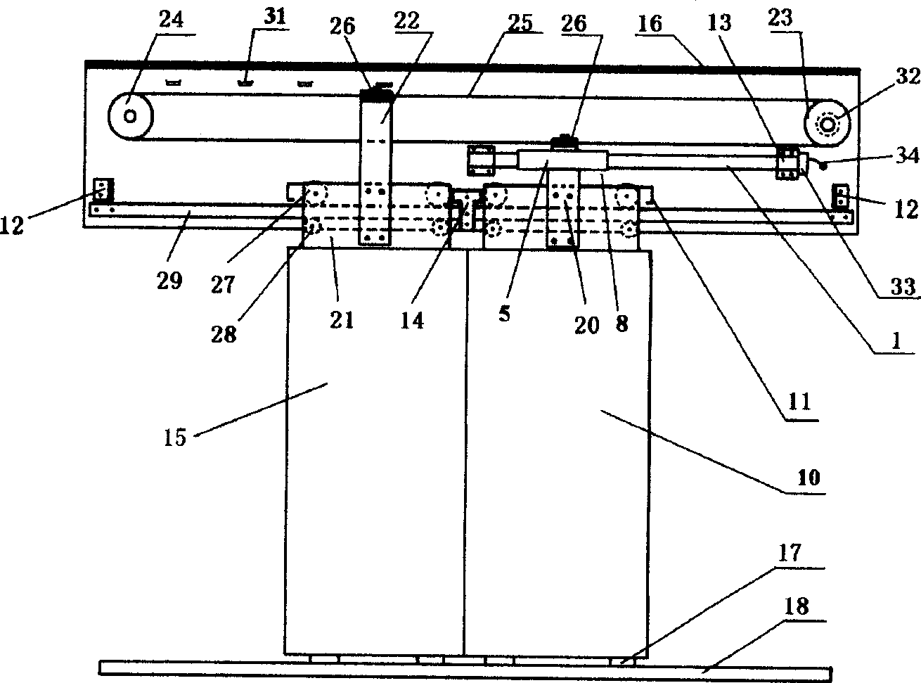
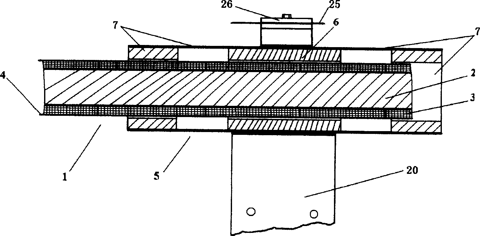
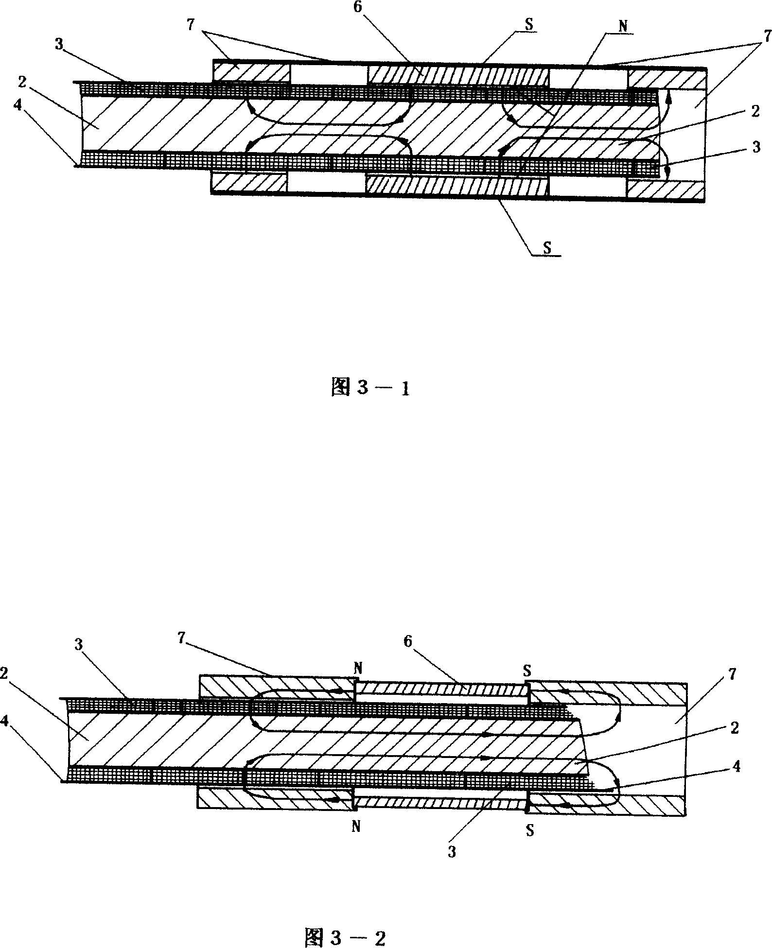
[0030] Embodiment 1: An embodiment of a DC linear motor and its car door device using a circular tubular permanent magnet mover, its cross-sectional structure is shown in the attached schematic diagram Pic 4-1 .

Embodiment 2

[0031] Embodiment 2: An embodiment of a DC linear motor and its car door device using a rectangular tubular permanent magnet mover. The cross-sectional structure is shown in the attached schematic diagram Figure 4-2 .

Embodiment 3

[0032] Embodiment 3: An embodiment of a car door device using a circular tubular permanent magnet mover DC linear motor and using permanent magnet attraction magnetic levitation technology. The cross-sectional structure is shown in the attached schematic diagram Figure 5-1 .


PUM


Abstract

Disclosed is a direct current linear motor drive elevator door, which uses moving-iron direct current linear motor as the directly-driving power source to elevator carriage door device, and samples the mechanical system of the door device. Compared with rotating variable-frequency door device and inductive variable-frequency door device, the manufacture of said device is simple, and the control system is also simple. Using low-voltage direct current makes the elevator door device is safe, reliable and without noise. And the magnetic levitation technique also can be introduced to make the device have more perfect property.

Description

technical field [0001] The invention relates to an automatic door driving device for an elevator car, in particular to an automatic door device for an elevator car using a moving iron type DC linear motor as driving power, and belongs to the field of driving devices for elevator car doors. Background technique [0002] Due to the need to meet the low speed and adjustable speed requirements of the elevator car door, the drive motor of the elevator car automatic door has been using a rotary DC motor with brushes for a long time. It has the following obvious disadvantages: the one is that the torque characteristics at low speeds are not good, so the motor must be allowed to work at a higher speed, and mechanical devices such as gears or pulleys are used to reduce the door speed. These additional devices not only occupy the already narrow ceiling space of the elevator car, increase the weight of the door control system, but also increase the failure rate and maintenance cost of ...

Claims


Application Information

Patent Timeline
Patent Type & Authority Applications(China)
IPC IPC(8): B66B13/08H02K41/035
Inventor 戴开煌
Owner 戴开煌
Learn More