Direct-driving (external-toothing) gear speed reducer
A gear reducer, direct-acting technology, applied in the direction of gear transmission, belt/chain/gear, transmission, etc., to achieve stable operation, improved bearing capacity, and light weight.
Inactive Publication Date: 2006-03-08
王维民
View PDF1 Cites 3 Cited by
- Summary
- Abstract
- Description
- Claims
- Application Information
AI Technical Summary
Problems solved by technology
But it also has some problems. There are related information: When the transmission ratio of the harmonic transmission reducer is tens of revolutions per revolution, its transmission efficiency is 90%. It has a transmission efficiency of 70%
Method used
View moreImage
Smart ImageViewing Examples

Examples
Embodiment Construction
Login to View More PUM
 Abstract
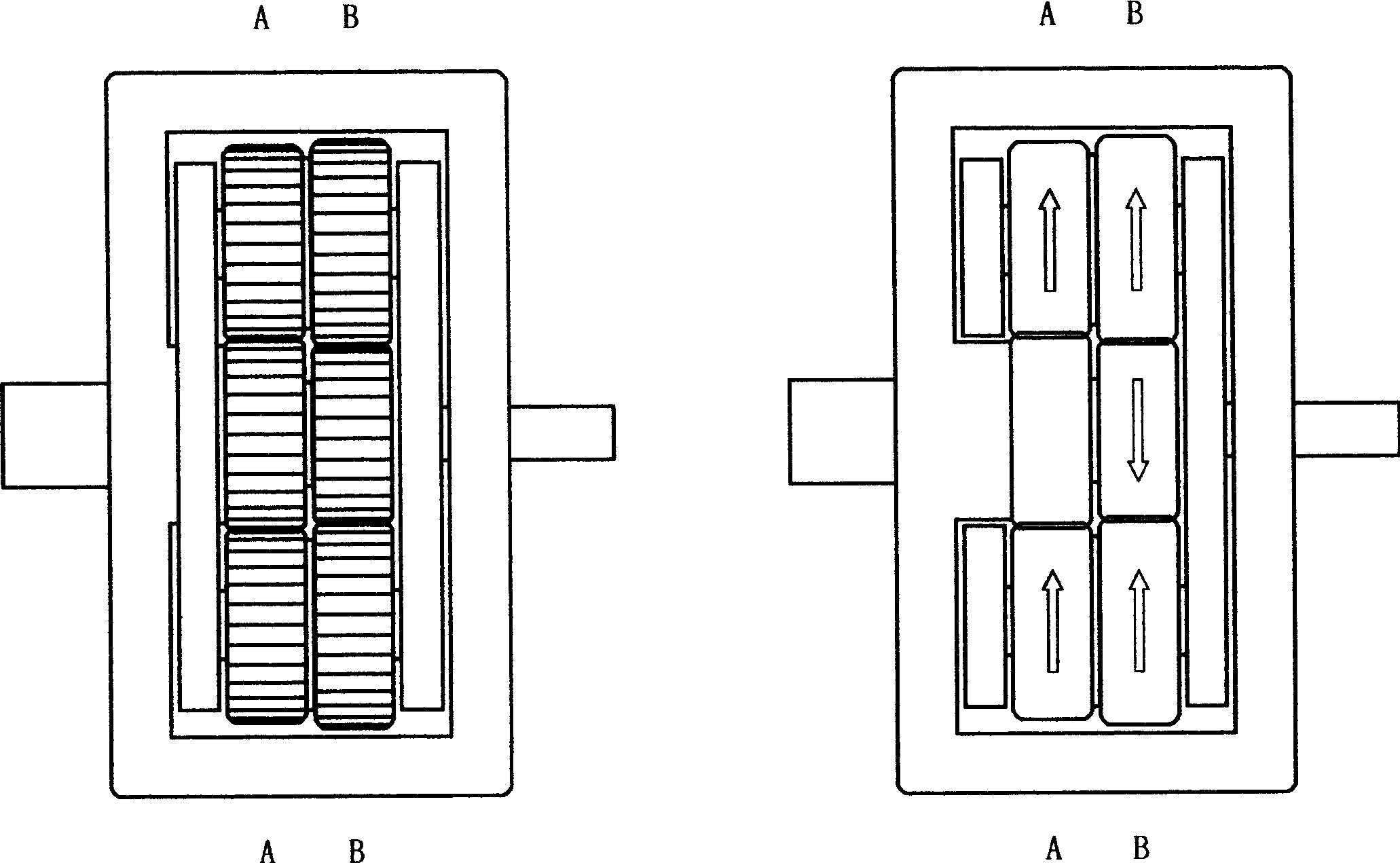
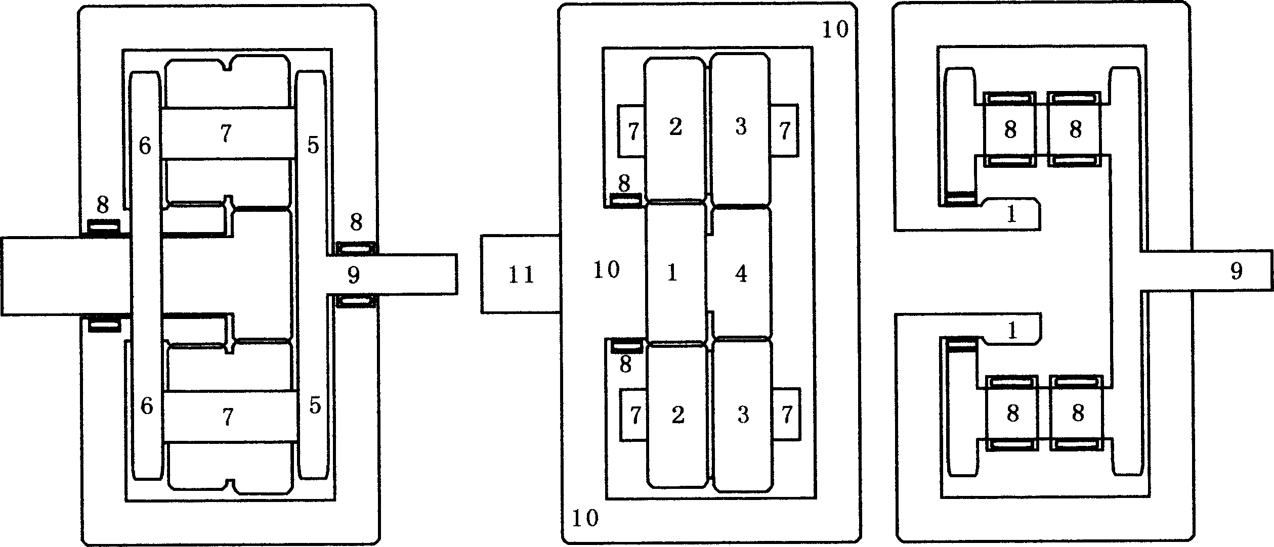
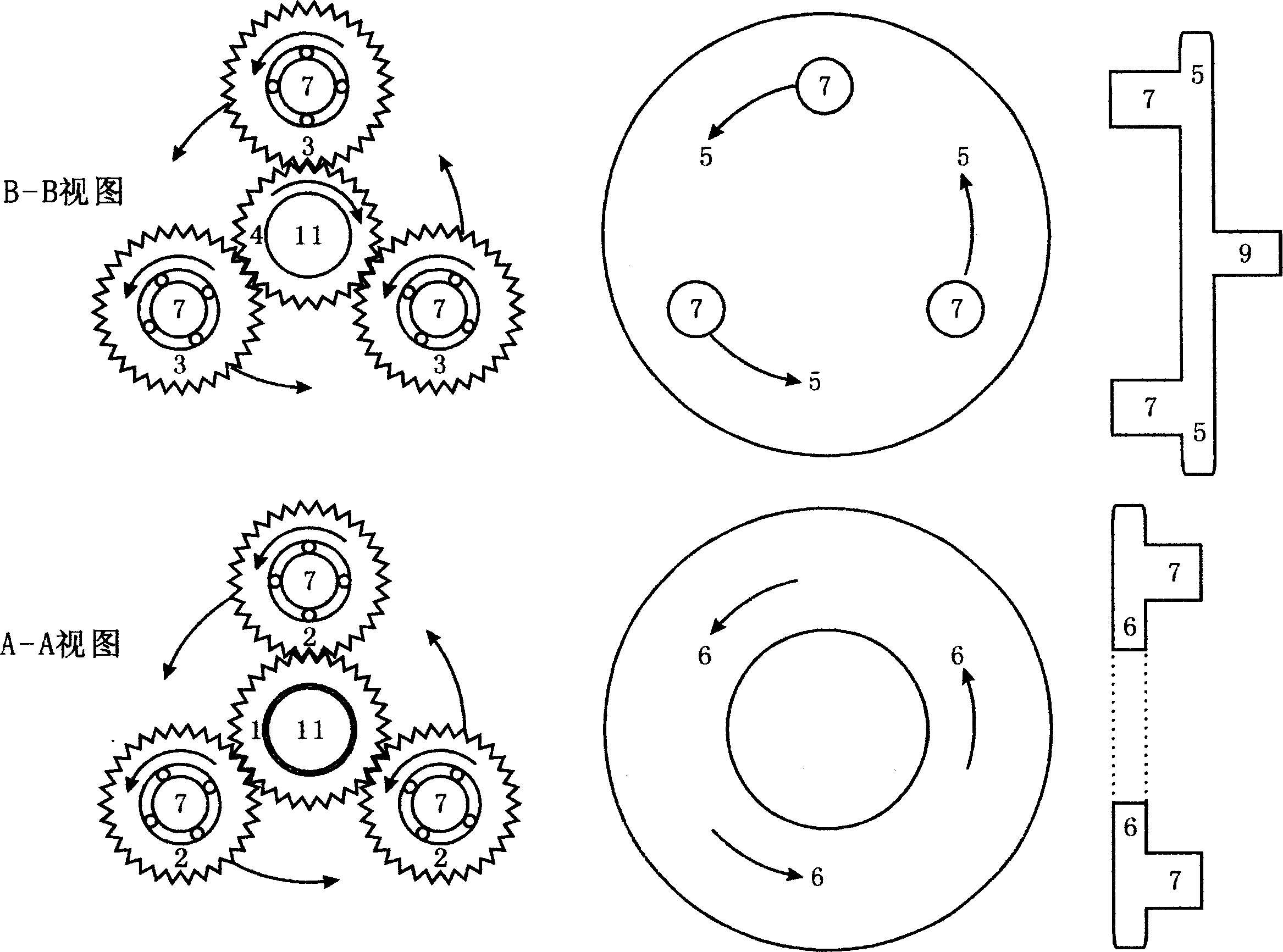
A direct driving (outer engaging) gear speed reducer, only adjusting the diameter ratio of two gears, various transmission ratio from tens to tens of thousands, in any transmission ratio, every gear driving output axle in minimum friction coefficient all the time, the loaded force in each gear is uniform by driving planetary gear set in accurate position. Said invention also can be used as speed increaser with increased bearing ability, simple structure, small volume and light weight.
Description
Technical field: The present invention relates to the technical field of speed reducer, because it is directly driven by lever arm balancing gravity, and all adopt external gear drive, so specifically it is a kind of "direct acting (external gear) gear reducer". Background technique: In the existing technical field, the harmonic drive reducer is a high-ratio reducer, and its first-stage retrieval transmission ratio can reach 500 revolutions per revolution, so it has a wide application prospect in high-ratio reduction equipment . But it also has some problems. There are related information: When the transmission ratio of the harmonic transmission reducer is tens of revolutions per revolution, its transmission efficiency is 90%. It has a transmission efficiency of 70%. Invention content: The object of the present invention is to provide a "direct-acting (external gear) gear reducer", which can overcome some deficiencies in the prior art. At the same time, compared with ...
Claims
Login to View More Application Information
Patent Timeline
 IPC IPC(8): F16H37/12F16H1/28
Inventor 王维民
Owner 王维民
Features
- R&D
- Intellectual Property
- Life Sciences
- Materials
- Tech Scout
- Unparalleled Data Quality
- Higher Quality Content
- 60% Fewer Hallucinations
Learn More Browse by: Latest US Patents, China's latest patents, Technical Efficacy Thesaurus, Application Domain, Technology Topic, Popular Technical Reports.
© 2025 PatSnap. All rights reserved.Legal|Privacy policy|Modern Slavery Act Transparency Statement|Sitemap|About US| Contact US: help@patsnap.com