Wet air-cooled condenser
An air-cooled condenser, wet-type technology, applied in evaporators/condensers, refrigerators, refrigeration components, etc., can solve problems such as low heat exchange efficiency, achieve enhanced heat exchange effect, reduce costs, and improve heat exchange efficiency. Effect
- Summary
- Abstract
- Description
- Claims
- Application Information
AI Technical Summary
Problems solved by technology
Method used
Image
Examples
Embodiment 1
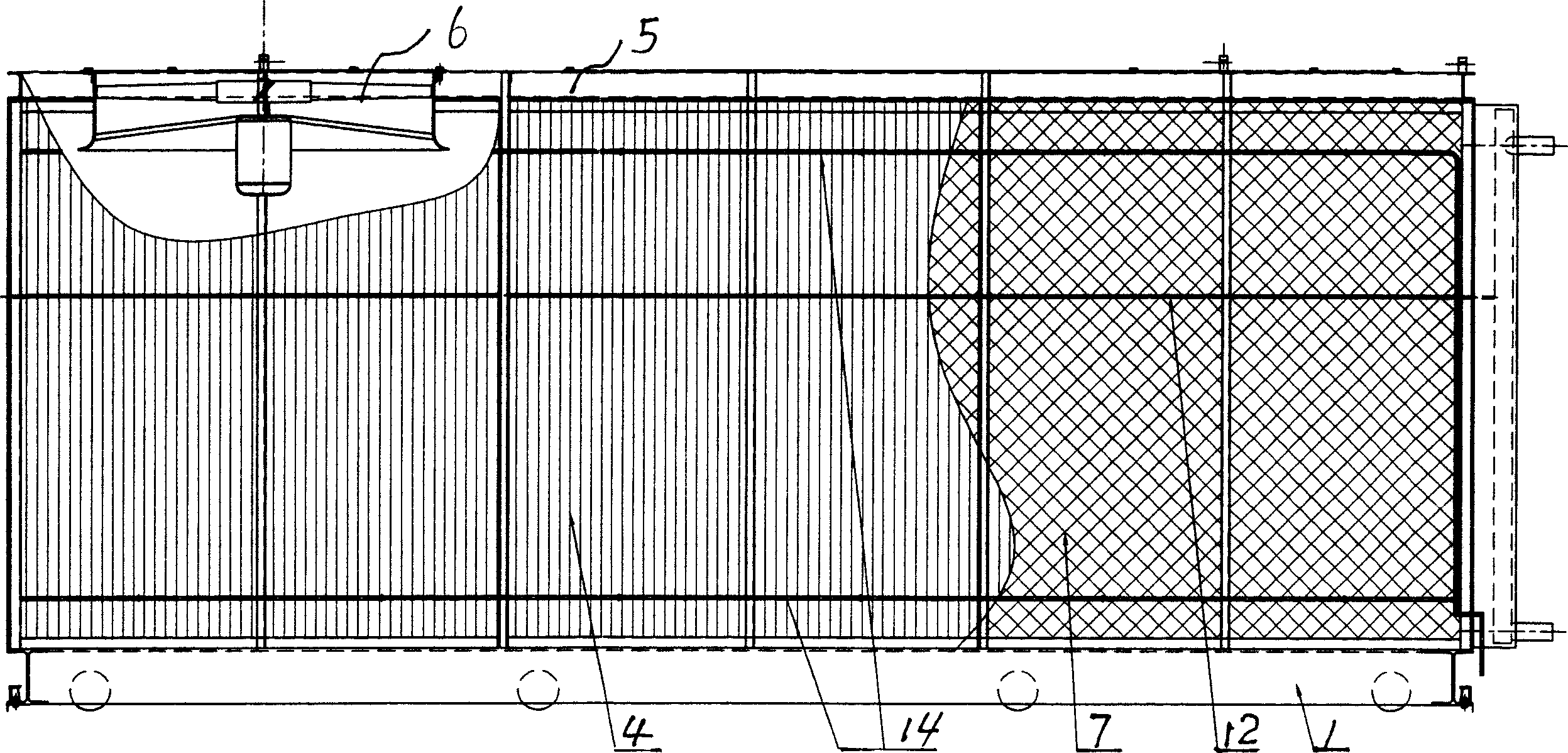
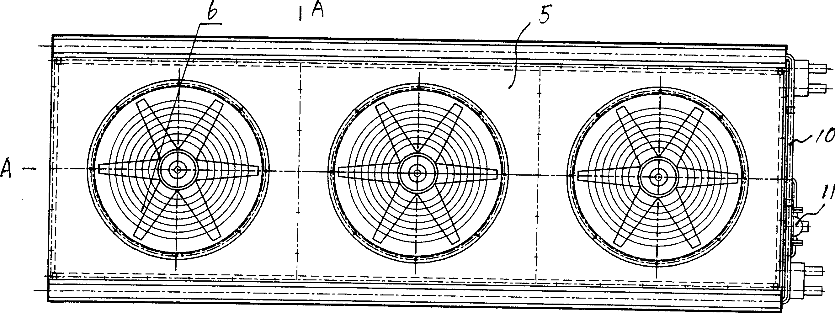
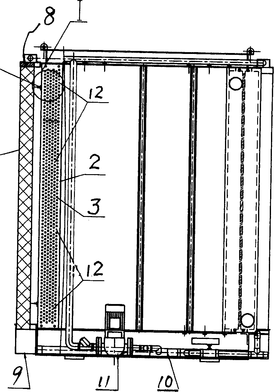
[0023] Such as figure 1 , 2 Shown: Same as the existing dry-type air-cooled condenser structure, there is a frame 1, and end plates 2 are connected to the left and right sides of the frame 1, and continuous copper pipes go back and forth between the end plates to form two rows of serpentines. Coil 3, the two ends of each section of copper tube are interference fit with the hole on the end plate, the coil 3 is connected with cooling fins 4; the frame 1 has a cover 5 and a fan fixed on the cover 6. The outer side of described coil pipe 3 is provided with vertical pre-cooling plate 7, and pre-cooling plate 7 can be the paper pad (Jiangyin celpad brand) that is fixed on the frame 1, and water distributor 8 is arranged on the pre-cooling plate 7, There is a sump 9 below the pre-cooling plate 7, and a circulating water pipe 10 and a water pump 11 are connected with the water distributor 8 and the sump 9.
[0024] When the ambient temperature is greater than 20°C, the water pump 1...
Embodiment 2
[0027] Such as figure 1 , 2 , Shown in 3, 4, 5: be provided with frame 1, be connected with end plate 2 at the left and right sides of frame 1, cover plate 5 and blower fan 6 fixed on the cover plate 5 are arranged above frame 1. The front and rear sides between the two end plates 2 are connected with a coil fixed slide bar 12, the two ends of the coil tube fixed slide bar 12 are fixedly connected with the end plate 2, and the middle part of the coil tube fixed slide bar 12 is in contact with the cooling fins 4. Then, the copper tube connected to the heat dissipation fin 4 passes through the hole 13 provided on the end plate 2 , and there is a gap between the copper tube and the hole 13 . Copper tubes, cooling fins 4 and coil tube fixing slide bars 12 are arranged in order from top to bottom between the two end plates 2 , and the copper tubes between the two end plates 2 are in a continuous serpentine shape, that is, the coil tube 3 . Other structures are with embodiment 1. ...
Embodiment 3
[0029] Such as figure 1 , 2 , shown in 3, 4, and 5: other structures can be the same as embodiment 1 or 2, but the coil pipe connected with the water pump 11 is provided with the coil cleaning pipe 14 on the top of the cooling fin 4 or the coil pipe 3, and the coil cleaning pipe 14 is provided. The pipe cleaning pipe 14 is provided with cleaning nozzles 15 . According to the dirt condition on the coil tube 3 or the cooling fins 4, the cleaning nozzle 15 can be opened to clean the dirt on the coil tube 3 or the cooling fins 4 in time.
[0030] The whole equipment can be controlled by microcomputer, and the water supply, drainage, and fan shutdown are all controlled by the computer and run automatically.
PUM
 Abstract
Description
Claims
Application Information
 - R&D
- Intellectual Property
- Life Sciences
- Materials
- Tech Scout
- Unparalleled Data Quality
- Higher Quality Content
- 60% Fewer Hallucinations
Browse by: Latest US Patents, China's latest patents, Technical Efficacy Thesaurus, Application Domain, Technology Topic, Popular Technical Reports.
© 2025 PatSnap. All rights reserved.Legal|Privacy policy|Modern Slavery Act Transparency Statement|Sitemap|About US| Contact US: help@patsnap.com


