Supercharge Your Innovation With Domain-Expert AI Agents!

Objective lens holder for an objective lens driving device

A technology of a driving device and an objective lens holder, which is applied in the field of objective lens holder, can solve the problems of high cost, reduced sensitivity, deterioration of inclination angle characteristics, etc., and achieves the effects of convenient assembly and thinning.

Inactive Publication Date: 2006-03-08
MITSUMI ELECTRIC CO LTD
View PDF6 Cites 0 Cited by
  • Summary
  • Abstract
  • Description
  • Claims
  • Application Information

AI Technical Summary

Problems solved by technology

[0016] In the conventional objective lens driving device with symmetrical structure disclosed in Patent Document 5, the tracking coil and the tilting coil must be pasted on the side of the objective lens holder, and there are problems of laborious and high cost in manufacture.
In addition, since air-core coils are much more expensive than wire-wound coils, the objective lens driver becomes expensive
In addition, since the structure is such that only one focusing coil is wound on the objective lens holder, it is necessary to pass the laser light under the lower surface of the objective lens holder, and it is difficult to reduce the thickness of the optical pickup.
[0017] On the other hand, the objective lens drive device with an asymmetric structure disclosed in Patent Document 6 is difficult to achieve weight balance because of its asymmetric structure, and there are problems such as unnecessary resonance easily occurring during mass production.
In addition, the manufacturing process of printing coils on printed circuit boards is complicated, and there is a problem of high cost compared with wound coils
In addition, it is necessary to perform complex multi-pole magnetization on the magnet, which is not only costly, but also becomes the main cause of decreased sensitivity to acceleration and deterioration of inclination angle characteristics due to the neutral region.

Method used


Image

  • Objective lens holder for an objective lens driving device
  • Objective lens holder for an objective lens driving device
  • Objective lens holder for an objective lens driving device

Examples


Embodiment Construction

[0034] Hereinafter, embodiments of the present invention will be described in detail with reference to the drawings.

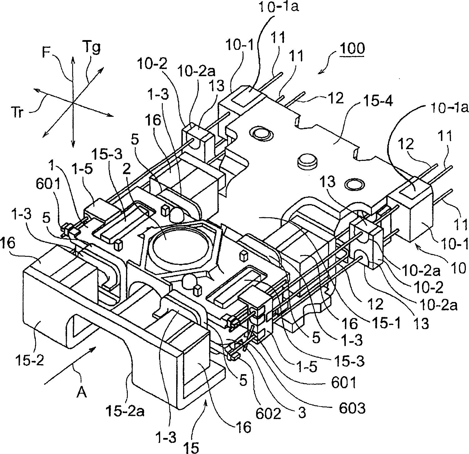
[0035] figure 1 It is a perspective view of an objective lens driving device 100 according to an embodiment of the present invention, showing a state in which a metal top cover (not shown) is removed.

[0036] Such as figure 1 As shown, the objective lens driving device 100 has an objective lens holder 1 . The objective lens holder 1 has a lens mounting portion (described later) formed of a through hole for mounting the objective lens 2 at a central position. On both sides of the lens mounting portion of the objective lens holder 1 in the tracking direction Tr, a pair of main winding frame portions (to be described later) for winding a tilt coil and a focus coil 3 to be described later are provided.

[0037] This main winding frame part is made open, so that the opening above it can expose a part of the yoke (to be described later). Among the four outer wa...


PUM

PropertyMeasurementUnit
wavelengthaaaaaaaaaa

Abstract

An objective lens holder for use in an objective lens driving device of a symmetry type has an upper member (50) and a lower member (55) assembled with the lower member. The lower member has a pair of main bobbin portions (552) for winding two tilting coils and two focusing coils. The pair of main bobbin portion is symmetrically disposed with respect to an optical axis of a laser beam. The upper member and the lower member have openings (505, 553) for passing through the laser beam. Each of the upper member and the lower member has four hook portions (504; 554) for winding four tracking coils.

Description

technical field [0001] The present invention relates to an objective lens driving device for an optical pickup of an optical disk drive, and in particular to an objective lens holder. Background technique [0002] Optical disc drives are used to read information recorded on optical discs (CD, CD-ROM, CD-R / RW, DVD-ROM, DVD-±R / RW, Blu-lay, HD, DVD), or write information installation. Such an optical disc drive has an optical pickup for irradiating laser light on the optical disc and detecting the reflected light in order to read information from the optical disc or write information into the optical disc. [0003] On the other hand, it is well known that, in DVD devices, there is an optical disc drive equipped with a special optical pickup for recording and reproducing both DVD and CD. This special optical pickup is an optical pickup that uses short-wavelength laser (wavelength about 650nm) for DVD and long-wavelength laser (wavelength about 780nm) for CD to record and repro...

Claims


Application Information

Patent Timeline
Patent Type & Authority Applications(China)
IPC IPC(8): G11B7/09G02B7/02
CPCG11B7/0935G11B7/0956G02B7/08G11B7/0933E03C1/046C02F1/001B01D35/02F16K19/006F16K31/605E03C1/0408A47K3/40E03C2201/30E03C2201/40
Inventor 山田司
Owner MITSUMI ELECTRIC CO LTD
Features
  • R&D
  • Intellectual Property
  • Life Sciences
  • Materials
  • Tech Scout
  • Unparalleled Data Quality
  • Higher Quality Content
  • 60% Fewer Hallucinations
Learn More