Multi-axis robot provided with a control system

A multi-axis robot and control system technology, applied in general control systems, control/regulation systems, program-controlled manipulators, etc., can solve complex problems, long working hours, etc. Effect

Active Publication Date: 2006-03-08
STAUBLI FAVERGES SA
View PDF3 Cites 9 Cited by
  • Summary
  • Abstract
  • Description
  • Claims
  • Application Information

AI Technical Summary

Problems solved by technology

These connections between the amplifier and the encoder make the work of installing these devices long and complicated

Method used


Image

  • Multi-axis robot provided with a control system

Examples


Embodiment Construction

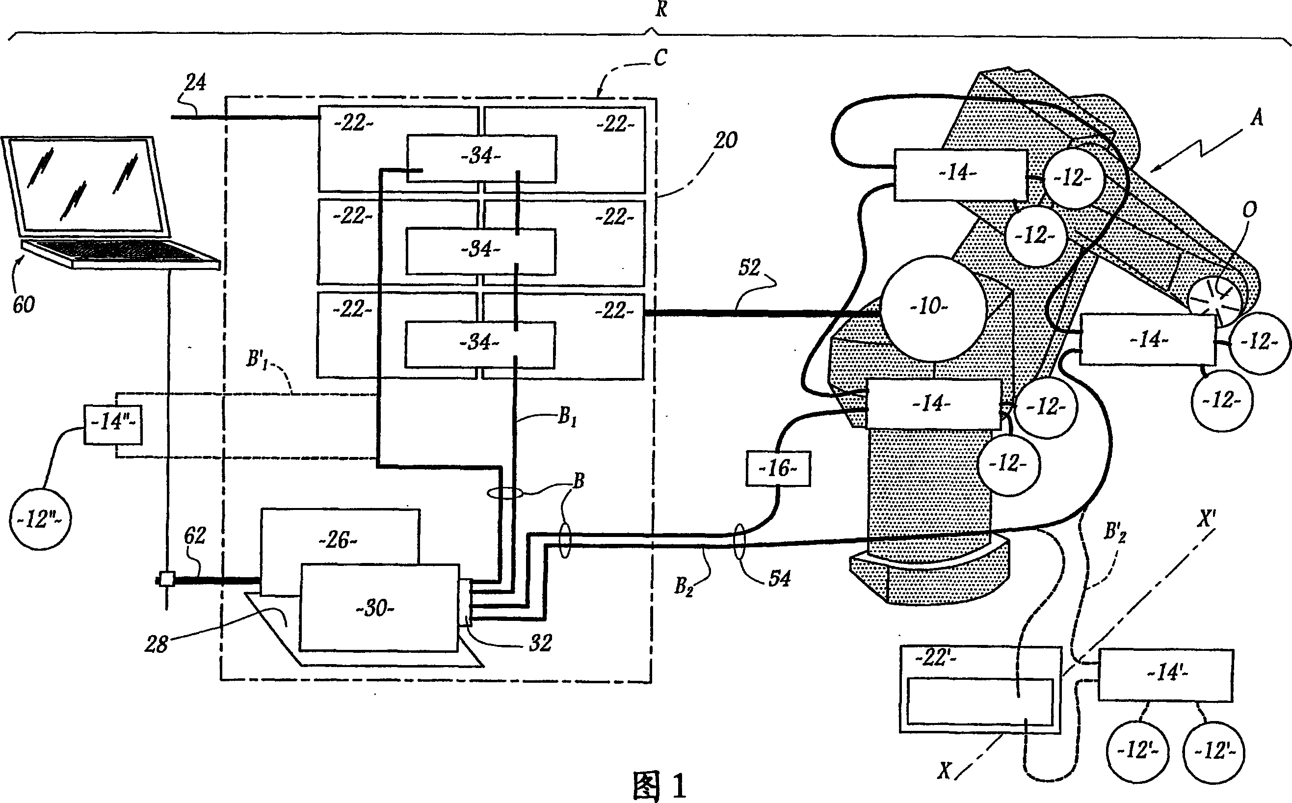
[0017] Through the following description of the embodiment of the multi-axis robot and its control system according to the invention, people can better understand the present invention and have a clearer understanding of other advantages. This embodiment is only given by way of example with reference to the accompanying drawings , where the simple graph is a theoretical rough representation of the associated control system and multi-axis robot.

[0018] The robot arm A of the robot R shown in the figure is arranged along the conveying path shown in the direction X-X'. The robotic arm is equipped with six motors, each of which moves the moving part of the robotic arm about one of the six axes of the robotic arm to move the tool O to a designated position. These electric motors are represented in the figure as mechanization 10 . In fact, they are distributed in the robot arm A. Distributed throughout the robot R are six analog position sensors or encoders 12 for measuring the ...


PUM


Abstract

The robot comprises: - a controller (C), including power modules (22) for supplying the motors (10) of the arm (A) of the robot (R), a CPU unit (26), for calculation and processing and connection means (52, B), between the arm (A), the power modules (22) and the CPU unit (26). The connection means (52, B) comprise a single functional bus (B) which connects a control unit (30), associated with the CPU unit (26), firstly to the power modules (22) and, also, to the digital interfaces (14) with the sensors (12) on the arms (A). Said interfaces (14) are either integrated with the arm (A) or located in the immediate vicinity thereof.

Description

technical field [0001] The invention relates to a multi-axis robot equipped with a control system. Background technique [0002] It is known to control a multi-axis robot by supplying the motors of the multi-axis robot with control signals generated by a computing and processing unit which determines the path of the robot. It is known, for example, from US-A-4,786,847 that, in order to make path calculations efficient, the above units can be operated in a closed-loop mode, using feedback signals from position sensors carried on the robot's manipulator. In known robots, a large number of cables have to be installed between the robotic arm and its control unit, which leads to long connections and wiring times and a non-negligible risk of errors, resulting in complex and expensive commissioning operations. [0003] From EP-A-0 777 167 it is known that a fiber optic bus can be used to connect a digital controller to amplifiers, each connected to an encoder by conventional lines...

Claims


Application Information

Patent Timeline
Patent Type & Authority Applications(China)
IPC IPC(8): G05B19/414B25J9/16
CPCY10T74/20311Y10T74/20305G05B2219/33218G05B2219/33162Y10T74/20317G05B2219/40237B25J9/1602Y10T74/20341G05B19/414Y02P90/02
Inventor V·热拉P·佩里拉J-M·博内德蒂韦
Owner STAUBLI FAVERGES SA
Why Eureka
Try Eureka