Lathe chuck
A technology of a clamping device and a lathe, applied to the device field of a lathe, can solve the problems of inconvenient installation and maintenance, affecting the clamping of the chuck to the workpiece, and being prone to loosening, etc., so as to facilitate assembly and maintenance, improve work stability, The effect of easy assembly and maintenance
- Summary
- Abstract
- Description
- Claims
- Application Information
AI Technical Summary
Problems solved by technology
Method used
Image

Examples
Embodiment Construction
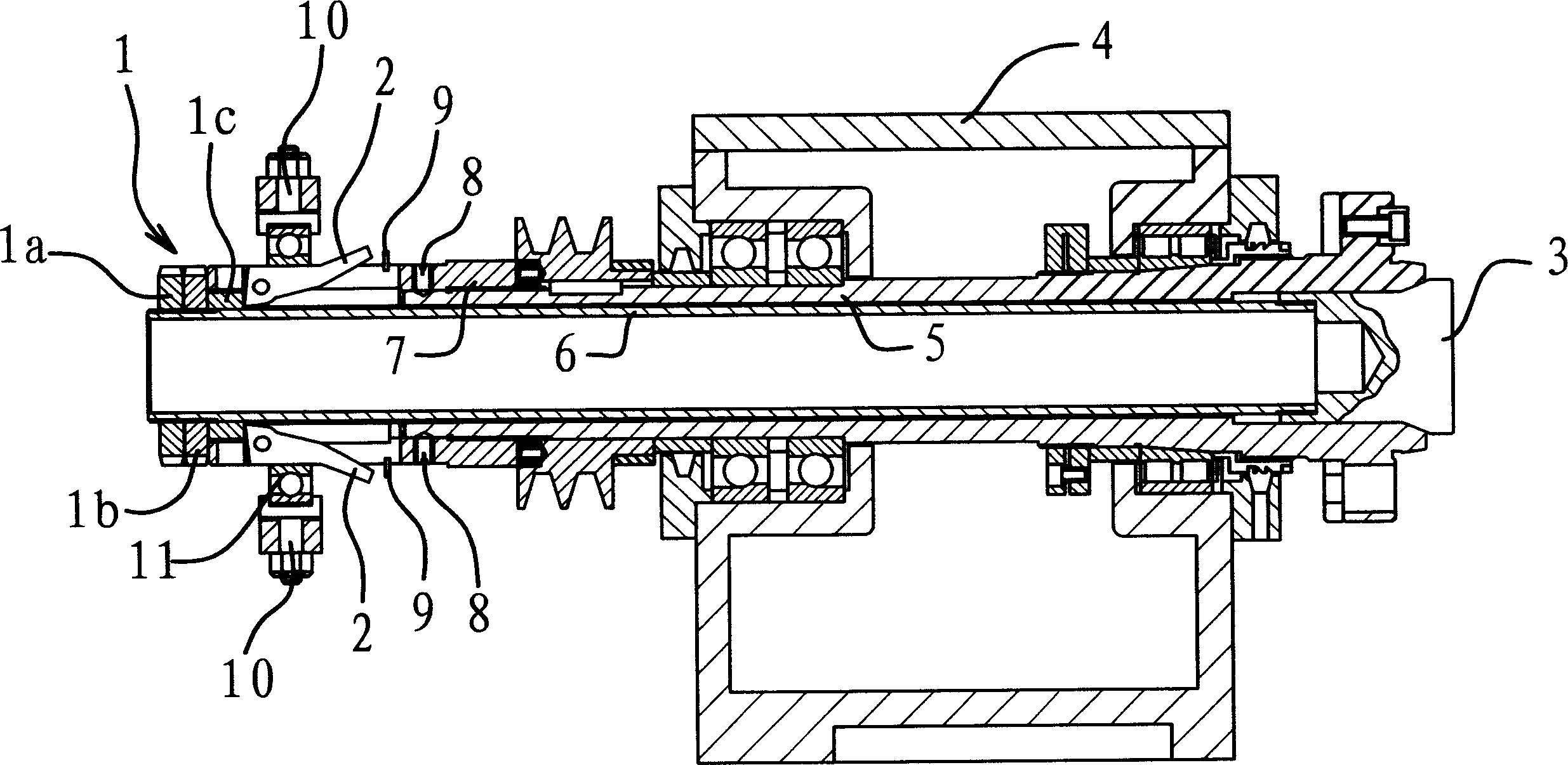
[0022] Such as figure 1 As shown, this lathe clamping device is assembled on the headstock 4, and it comprises the main shaft 5 that is located on the headstock 4 and the draw tube 6 that is located in the main shaft 5, and the two ends of the main shaft 5 stretch out the headstock 4 . One end of the draw tube 6 is fixedly connected with a collet 3 , and the other end stretches out from the main shaft 5 . The collet 3 is located at the end of the main shaft 5, and a conical surface that can cooperate with each other is provided between the main shaft 5. Under the action of the tapered surface, the chuck 3 can clamp and loosen the workpiece.
[0023] A clamping jaw base 7 is sleeved on the extension part of the drawing tube 6 protruding from the main shaft 5 , and the clamping jaw base 7 is threadedly connected to the end of the main shaft 5 . Several opening slots are arranged on the jaw base 7, and a jaw 2 is respectively hinged in each opening slot. On the outer side of ...
PUM
 Abstract
Description
Claims
Application Information
 - R&D
- Intellectual Property
- Life Sciences
- Materials
- Tech Scout
- Unparalleled Data Quality
- Higher Quality Content
- 60% Fewer Hallucinations
Browse by: Latest US Patents, China's latest patents, Technical Efficacy Thesaurus, Application Domain, Technology Topic, Popular Technical Reports.
© 2025 PatSnap. All rights reserved.Legal|Privacy policy|Modern Slavery Act Transparency Statement|Sitemap|About US| Contact US: help@patsnap.com