Interlocking tooth bond for assembly of fiber composite laminates

一种纤维复合、叠片的技术,应用在家用元件、应用、车辆部件等方向,能够解决接头复杂等问题,达到增加气动平滑性、减少重量、能量吸收增加的效果

Inactive Publication Date: 2006-03-22
BELL HELICOPTER TEXTRON INC
View PDF0 Cites 2 Cited by
  • Summary
  • Abstract
  • Description
  • Claims
  • Application Information

AI Technical Summary

Problems solved by technology

Curvature complicates all these joints
Thus, while these methods represent a significant advance in joining fiber composite laminates, considerable disadvantages remain

Method used


Image

  • Interlocking tooth bond for assembly of fiber composite laminates
  • Interlocking tooth bond for assembly of fiber composite laminates
  • Interlocking tooth bond for assembly of fiber composite laminates

Examples


Embodiment Construction

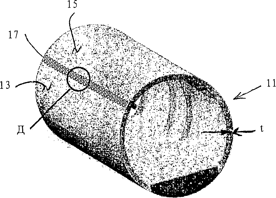
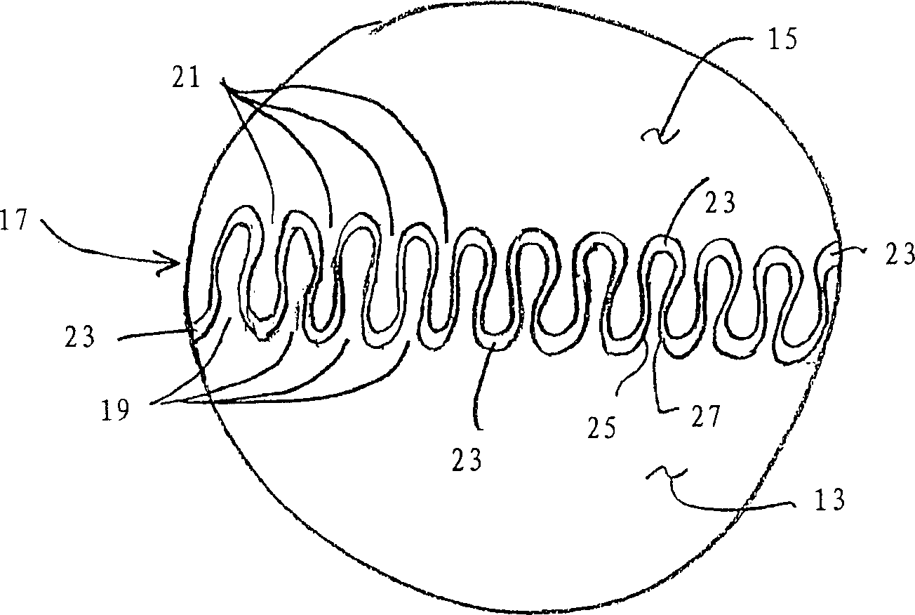
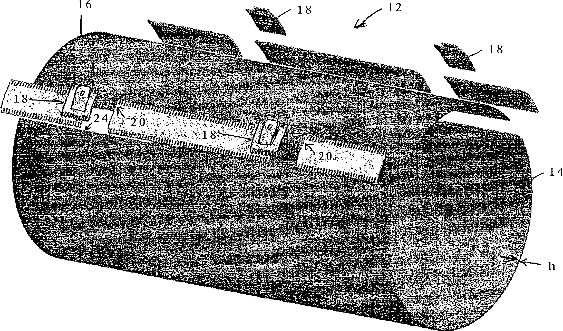
[0028] The present invention is an improved method of joining two fiber composite laminates together in an end-to-end manner. This method produces an unobtrusive adhesive bond to structurally join two fiber composite laminates together. There are two main embodiments of the invention: (1) mechanically interlocking teeth; (2) non-interlocking teeth. It will be appreciated that many combinations of interlocking teeth, non-interlocking teeth, offset interlocking and non-interlocking teeth may be used depending on the application in which the laminations are used. The tooth-type engagement of the present invention virtually eliminates peeling of the adhesive joint, thus reducing the potential for interlaminar failure. Laminations joined using the method of the present invention have greatly improved damage tolerance relative to conventional lap joints. The geometry of the joint inhibits disjointed cracks from propagating down the length of the joint and causing catastrophic fail...


PUM


Abstract

A method of forming a joint between the ends of two fiber composite laminates (13,15) comprises cutting a first set of teeth (19) in the end of the first fiber composite laminate cutting a second set of teeth (21) in the end of the second fiber composite laminate, the second set of teeth being matingly aligned with the first set of teeth; spatially aligning the first fiber composite laminate and the second fiber composite laminate so as to produce a bond line (23) having a variable thickness therebetween, the thickness being defined as a marginal distance between the first set and the second set of teeth; wherein the bond line is thickest near the tips of the teeth and thinnest near the midpoint of the teeth; disposing an adhesive in the bond line; applying a cover piece (123a,123b) over at least one surface of the joint, the cover piece being adapted to provide a visual indication of a level of strain in the joint; and curing the adhesive.

Description

[0001] technical field [0002] This invention relates to the joining of fiber composite laminates. Background technique [0003] Fiber composite laminates have been used for many years. They are a high strength, low weight option compared to metal components. Fiber composite laminations are especially suitable for use in the aircraft industry where weight reduction and strength gains are of utmost importance. [0004] Fiber composite laminates are formed by building multiple layers, sheets or laminates of composite fibers one layer after the other. The fibers of each layer are oriented in a specific direction to give the laminate special properties. In a conventional laminate, some fibers run parallel to the longitudinal axis, some fibers run transverse to the longitudinal axis, and some fibers run "off-axis" at various angles about the longitudinal axis. By placing and orienting the fiber layers in a defined configuration, the stiffness and other properties of the lamina...

Claims


Application Information

Patent Timeline
Patent Type & Authority Applications(China)
IPC IPC(8): B29C59/00B29C59/02B65H21/00B29C65/00B29C65/50B32BB32B7/08B32B7/12
CPCB32B3/02B29L2031/3082B29C65/54B64C1/068B29C66/2276B29C66/02241B32B7/12Y02T50/433B29L2031/7126B29C2793/0081B29C66/20B29C66/223B29C66/4322B64C1/12B29C65/4835B29C66/0224Y02T50/43B29C65/483B29C66/43B32B7/08B32B17/02B29C66/2272B29C65/5042B29C65/8253B29C66/022B29C53/40B29C65/542B29C66/2274B29K2105/06B64C2001/0072B29C66/721B29C65/56B29C66/1142B29C66/227B29C66/72141B29C66/221Y10T156/1066Y10T428/17Y10T428/19Y10T428/193Y10T428/198Y10T428/197Y10T428/192Y10T428/195Y02T50/40B29C65/00B32B2262/101B32B2605/18B32B5/26
Inventor 詹姆斯·D·赫思科克罗德尼·H·琼斯
Owner BELL HELICOPTER TEXTRON INC
Why Eureka
Try Eureka