Micro-internal mixed catalytic burner

A catalytic burner and internal mixing technology, applied in the direction of burners, gas fuel burners, combustion methods, etc., can solve the problems of unsafe pre-mixed combustion gas, large structure of micro burners, etc., and achieve the advantages of preheating and The effect of safety, compact structure and uniform temperature distribution of the equipment

Inactive Publication Date: 2006-03-29
ZHEJIANG UNIV
View PDF1 Cites 4 Cited by
  • Summary
  • Abstract
  • Description
  • Claims
  • Application Information

AI Technical Summary

Problems solved by technology

[0004] In order to solve the problems in the prior art that the structure of the micro burner is relatively large and the premixed combustion gas outside the combustion chamber is unsafe, the present invention provides a kind of micro-combustor processed by micro-electromechanical system technology (MEMS), which is mixed inside the combustion chamber. Micro Internal Mixing Catalytic Combustor for Fuel Gas and Oxidant

Method used


Image

  • Micro-internal mixed catalytic burner
  • Micro-internal mixed catalytic burner
  • Micro-internal mixed catalytic burner

Examples


specific Embodiment 1

[0027] The structure of the miniature internal mixing type catalytic burner in the specific embodiment 1 is as Figure 1 to Figure 6 shown.

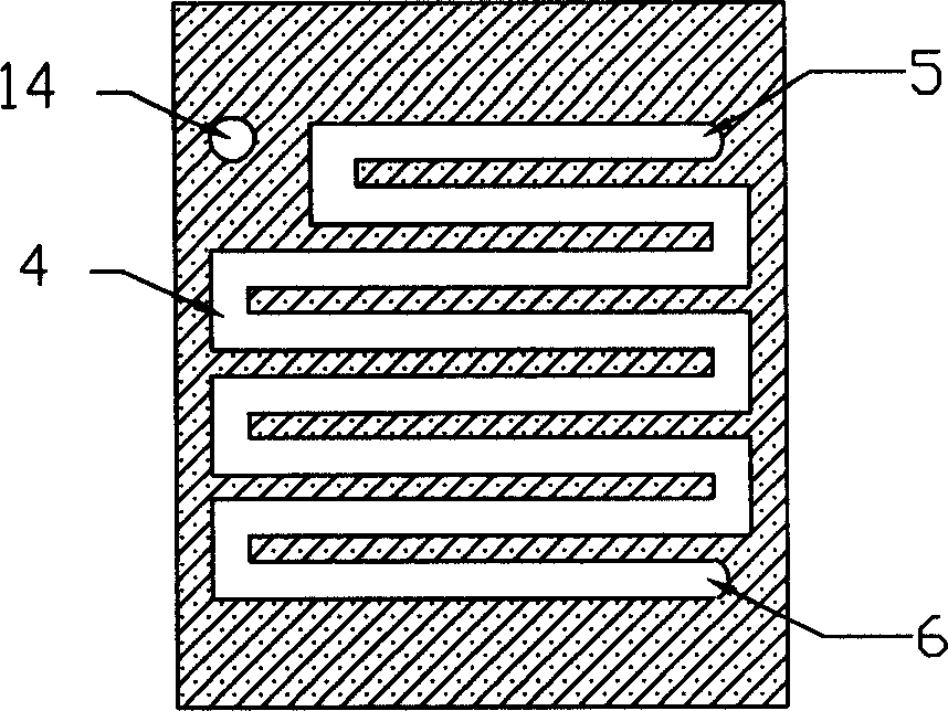
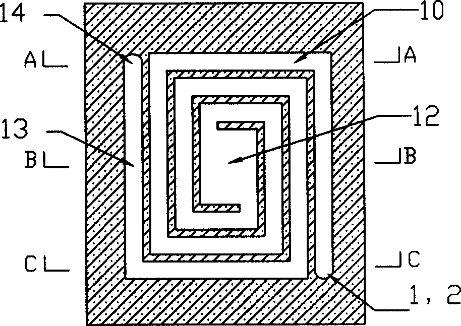
[0028] The micro internal mixing catalytic burner is made of single crystal silicon material, including the upper preheating chamber 1, the combustion chamber 2 and the lower preheating chamber 3, the upper and lower preheating chamber 1, the lower preheating chamber 3 and the upper and lower surfaces of the combustion chamber 2 Bonding forms a three-layer structure.

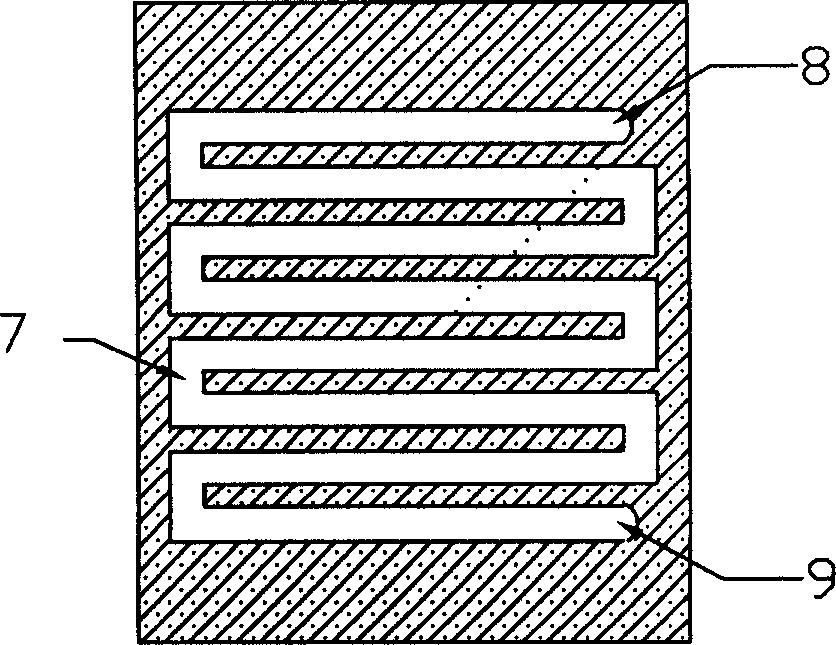
[0029] The inside of the upper preheating chamber 1 and the lower preheating chamber 3 are respectively etched by MEMS processing, and the upper preheating chamber preheating channel 4 and the lower preheating chamber 7 are respectively etched outside the upper preheating chamber and the lower preheating chamber. The upper preheating chamber preheating channel inlet 5 and the lower preheating chamber preheating channel inlet 8 are formed on the surface. The preheating pa...


PUM


Abstract

The invented catalytic combustor includes combustion chamber of monocrystal silicon material, upper preheating chamber and lower preheating chamber, its upper and lower surfaces are bonded and formed into three-layer structure; in the upper and lower preheating chambers respectively an etched preheating channel is set, and the combustion chamber interior is successively equipped with mutually-communicated etched premixing channel, combustion zone space and exhausting channel. Its structure is compact and can raise combustion efficiency.

Description

technical field [0001] The invention relates to a combustion device, in particular to a micro internal mixing catalytic burner which mixes fuel gas and oxidant inside the burner. Background technique [0002] Compared with traditional combustion, micro-combustion occurs in a larger scale range. The micro-combustion currently studied generally occurs in a small scale range, usually below 1cm. 3 occurs within the volume. The energy generated by micro-combustion has a broad application prospect as an energy provider in micro-electromechanical systems, micro-aerospace equipment, personal mobile electronic devices and other devices. Compared with batteries, micro-combustion has the characteristics of energy density dozens of times higher than batteries, low price, stable output voltage, less environmental pollution and convenient fuel addition. [0003] The currently researched micro-combustors can directly output thermal energy or output energy in the form of direct conversion...

Claims


Application Information

Patent Timeline
Patent Type & Authority Applications(China)
IPC IPC(8): F23D14/02F23D14/66
CPCY02E20/34
Inventor 周俊虎岑可法杨卫娟刘建忠程军周志军黄镇宇
Owner ZHEJIANG UNIV
Why Eureka
Try Eureka