Shaft seal device used for ultra low specific rotating speed centrifugal fan

A technology of centrifugal fan and specific speed, which is applied to components, mechanical equipment, machines/engines, etc. of pumping devices used for elastic fluids, and can solve the problem of inability to achieve small or even zero leakage, large vibration of fans and units , Fan impeller diameter and other issues, to shorten the installation and maintenance time, improve life, reduce the effect of temperature rise

Inactive Publication Date: 2006-04-12
SHANGHAI JIAO TONG UNIV
View PDF0 Cites 5 Cited by
  • Summary
  • Abstract
  • Description
  • Claims
  • Application Information

AI Technical Summary

Problems solved by technology

Ultra-low specific speed centrifugal fans have high pressure. If ordinary mechanical seals are used, the number and structure of the seal rings generally cannot meet the requirements of small leakage or even zero leakage.
Secondly, in order to improve efficiency, this type of fan often adopts a backward-facing impeller, and the diameter of the fan impeller

Method used


Image

  • Shaft seal device used for ultra low specific rotating speed centrifugal fan
  • Shaft seal device used for ultra low specific rotating speed centrifugal fan

Examples


Embodiment Construction

[0016] The technical solution of the present invention will be further described in detail below in conjunction with the accompanying drawings.

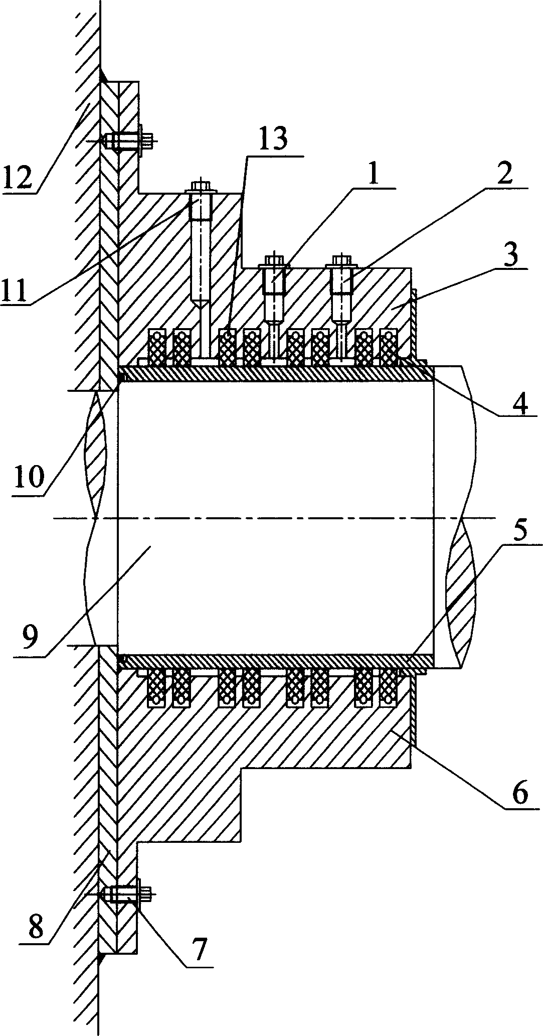
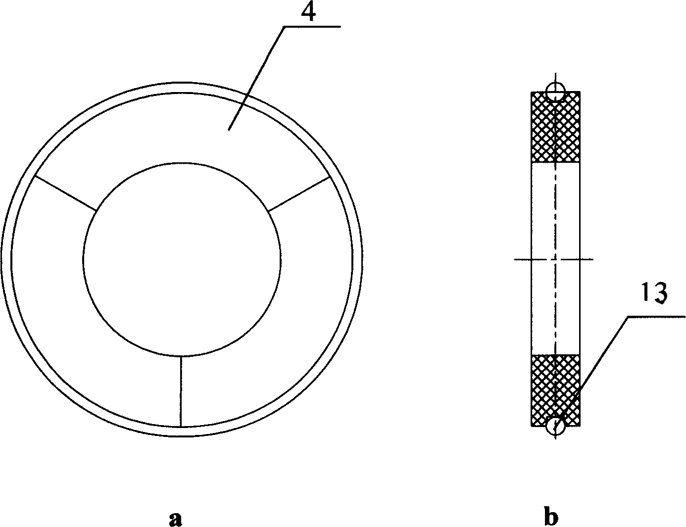
[0017] The structure of the shaft sealing device used for the ultra-low specific speed centrifugal fan of the present invention is as follows: figure 1 As shown, a horizontally split structure is adopted, and the shaft sleeve 5 is installed on the fan main shaft 9 through interference fit. The upper cover plate 3 and the lower cover plate 6 fixed on the outside of the shaft sleeve 5 are semicircular pairs of upper and lower sides, and the upper and lower cover plates are respectively connected by The bolt 7 is connected with the flange 8, and the flange 8 is installed on the rear end cover 12 of the fan casing by welding. The insides of the upper cover plate 3 and the lower cover plate 6 in contact with the shaft sleeve 5 are respectively provided with annular grooves for installing the sealing ring 4 . The sealing rings 4 are in gr...


PUM


Abstract

A shaft seal for the centrifugal blower with ultra-low rotation speed ratio features that 4-6 group of 8-12 sealing rings, which has slot on its surface for arranging flat spring in it, are installed in the annular slots on the upper and lower cover plates fixed at outsides of the shaft sleeve of the mainshaft of blower, the flanges of upper and lower cover plates are welded to the back end cover of the casing of blower, and said upper cover plate has two oil holes and an air hole for filling lubricating oil and inertial gas.

Description

technical field [0001] The invention relates to a shaft sealing device, in particular to a shaft sealing device for an ultra-low specific speed centrifugal fan, and belongs to the technical field of sealing of mechanical products. Background technique [0002] A mechanical seal is a shaft seal device for a rotating machine. At present, mechanical seals are widely used in fluid mechanical products, and with the improvement of product technology and the requirement of energy saving, the application prospects of mechanical seals will be more extensive. The sealing effect of the mechanical seal will directly affect the operation of the whole machine, especially in the petrochemical field, due to the presence of flammable, explosive, volatile, highly toxic and other media, the leakage of the mechanical seal will seriously affect the normal production, seriously There will also be major safety accidents. Thereby the sealing work is not done well, safety is not guaranteed, and pr...

Claims


Application Information

Patent Timeline
IPC IPC(8): F04D29/12
Inventor 杨波谷传纲王彤毛福芳
Owner SHANGHAI JIAO TONG UNIV
Why Eureka
Try Eureka