Digital model integral design method of complex product based on file

A technology for integrated design and complex products, applied in the field of integration, can solve problems such as affecting the coupling effect, difficult to solve comprehensive design, and difficult to adapt to the overall performance requirements of aerospace products, so as to achieve the effect of improving performance

Active Publication Date: 2006-04-12
中国航天科技集团公司第一研究院
View PDF0 Cites 15 Cited by
  • Summary
  • Abstract
  • Description
  • Claims
  • Application Information

AI Technical Summary

Problems solved by technology

These models can meet the needs of independent design and analysis of various disciplines, but it is difficult to solve the comprehensive design problem of mutual coupling and mutual restriction among various disciplines
With the advancement of science and technology, it is difficult to adapt to the increasing overall performance requirements of aerospace products by using traditional complex product development methods, especially the emergence of system integration and MDO technology, so that the complex problem of multiple mathematical models affecting the coupling effect can be solved

Method used


Image

  • Digital model integral design method of complex product based on file
  • Digital model integral design method of complex product based on file
  • Digital model integral design method of complex product based on file

Examples


Embodiment 1

[0030] Embodiment 1, the integrated design method of Pro / E software design model.

[0031] The selected design variables in the modeling process must be parameterized, and a relational expression must be established, and the process files are packaged through the method of file packaging, so as to realize the parameterization and optimal design of the model. The specific process is as follows:

[0032] (1) Model establishment and parameterization

[0033] a. Definition of parametric dimensions in sketches

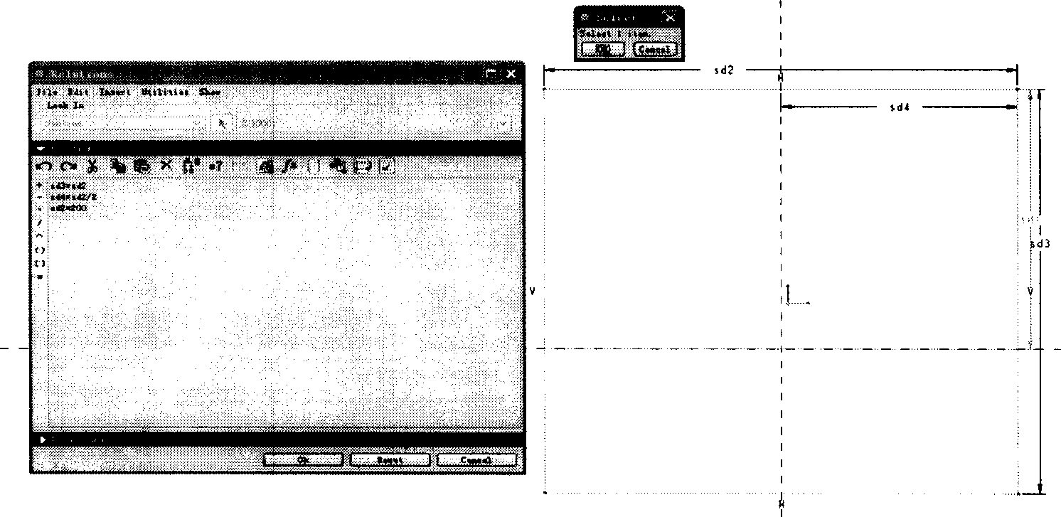
[0034] The parameterization of the integrated model is realized through the parameterization of the sketch drawing and the definition of the relationship in the 3D model. In the sketch drawing, the parameters to be parameterized should be defined. In the sketching interface, select the menu Tools>Relations to define the parameter relational expression, such as image 3 shown.

[0035] b. Definition of relational expressions in 3D model

[0036] In a 3D model, defining s...

Embodiment 2

[0043] Embodiment 2, integration of Patran / Nastran finite element analysis model

[0044] The selected design variables in the modeling process are parameterized to complete the parametric modeling, edit the command flow file in the process of building the model to form a process file, and package the process file through the method of file packaging, so as to realize the model Parametric and optimized design. Specific steps are as follows:

[0045] (1) Model establishment and parameterization

[0046] First, determine the key variables that need to be parameterized before building the model. These key variables mainly include the important dimensions in the model geometry, the density control value of the finite element grid, the value of the applied load, the size of the finite element element section properties, etc. .

[0047] To build a model in Patran, first define the key variables, and then use the variables to build a parameterized model in the process of building ...

Embodiment 3

[0054] Embodiment 3, the Matlab integration based on M file, concrete process is as follows:

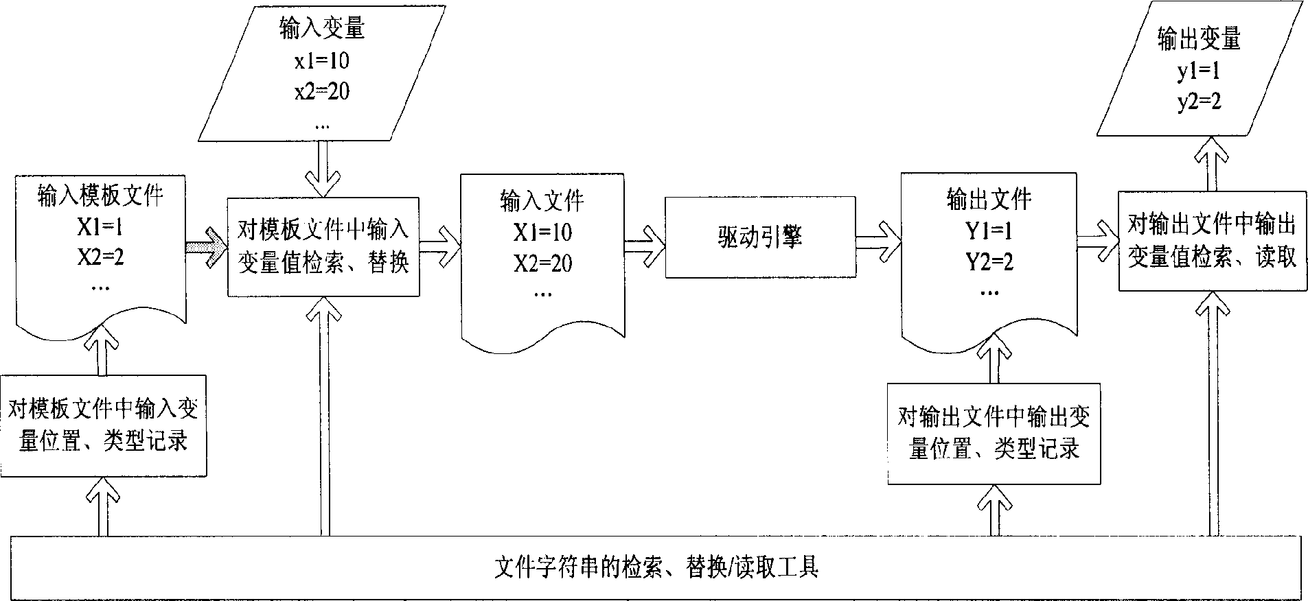
[0055] (1) Summarize and extract the problems of Matlab integration, and define input variables, input files, M files, output variables, and output files. For the case where multiple files are related to each other, the interface problem of data transmission between different files is handled well. PID controller closed-loop control model integration, such as Image 6 As shown, the transfer function graph of the system is shown as Figure 7 shown.

[0056] Input variables: given system Plant parameters (a1, a2), controller PID parameters KP, KI, KD

[0057] Output variable: the error e between the input and output of the closed-loop system

[0058] (2) Write the M file, including the problem-solving function statement, the input variable reading function statement, and the output variable written into the output file through the function statement in a fixed format.

[0059] PID...


PUM


Abstract

This invention relates to an integrated design method for digital models of complicated products based on files, which sets up models of commercial engineering soft and self edited software, determines the input variables to generate input files and templet files used for drive, generates data and files of the analysis results, determining the data format of the output variables and output result files, records the formats, position and the data kinds of the input variables in the templet file by an index tool of a file packaging device and finishes the record of the output variable position, format and data kinds to replace the input variables in the templet file to generate new input files, sets up models to the input files again to compute and generate new output files and carry out searches and fetch to the output variables in the output files to finish automatic integration finally.

Description

Technical field [0001] The invention relates to an integration method suitable for complex product design process, in particular to a file-based complex product digital model integration design method. Background technique [0002] In the development process of complex aerospace products, there are a large number of design and analysis models in various disciplines including overall, aerodynamics, flight mechanics, propulsion, control, and structure, such as: three-dimensional structural models, structural finite element models of the whole system or special sections , aerodynamic calculation model, dynamic strength analysis model, etc.; in addition, there are many self-developed software calculation models. These models can meet the needs of independent design and analysis of various disciplines, but it is difficult to solve the comprehensive design problem of mutual coupling and mutual restriction among various disciplines. With the advancement of science and technology, ...

Claims


Application Information

Patent Timeline
Patent Type & Authority Applications(China)
IPC IPC(8): G06F17/50
Inventor 陈海东赵雯沈重王悦
Owner 中国航天科技集团公司第一研究院
Why Eureka
Try Eureka