Superstructure of engine

An engine and structure technology, applied in the direction of engine starting, engine cooling, engine components, etc., can solve problems such as oil hammer, increase cost, damage connecting rod, etc., and achieve the effect of preventing assembly errors, rapid assembly, and simple assembly

Inactive Publication Date: 2006-04-12
YANMAR CO LTD
View PDF3 Cites 5 Cited by
  • Summary
  • Abstract
  • Description
  • Claims
  • Application Information

AI Technical Summary

Problems solved by technology

As a result, excess oil enters the combustion chamber and, as a result, there is a risk of oil hammer and damage to the connecting rod, etc.
And when the injection path of the starting aid is additionally set, the cost will be increased

Method used


Image

  • Superstructure of engine
  • Superstructure of engine
  • Superstructure of engine

Examples


Embodiment Construction

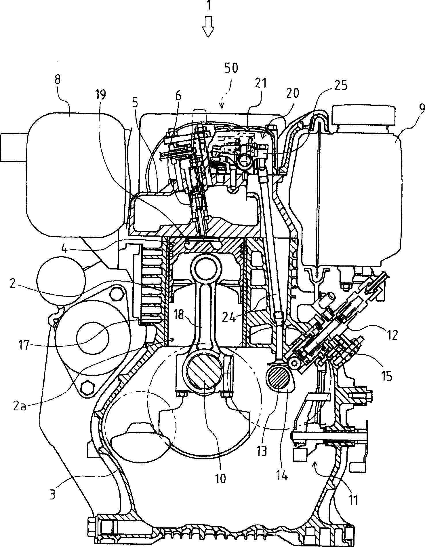
[0046] First, use Figure 1 to Figure 3 The overall structure of the engine 1 of the present invention will be described.

[0047] The engine 1 consists of a cylinder block 2 constituting the upper part of its main body, and a crankcase 3 constituting the lower part of its main body. The cylinder block 2 forms a cylinder 2a in the vertical direction at the center thereof, and accommodates the piston 4 in a cylinder liner 17 inside the cylinder 2a so as to be slidable in the vertical direction. Below the cylinder block 2 , a crankshaft 10 is pivotally supported by the crankcase 3 in the front-rear direction, and the crankshaft 10 and the piston 4 are connected by a connecting rod 18 .

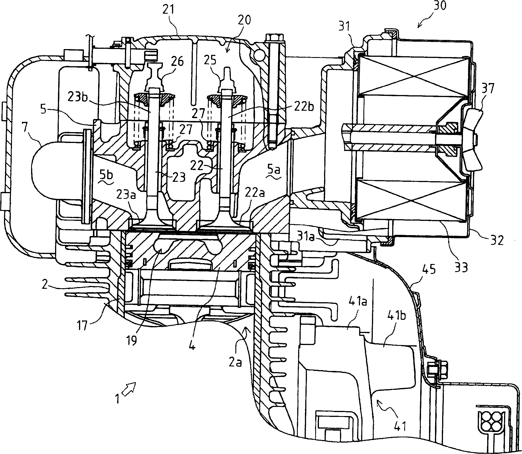
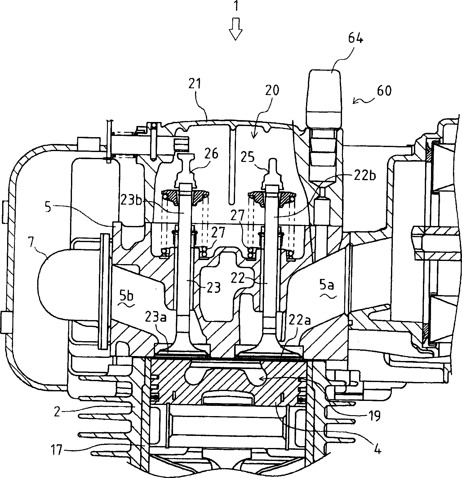
[0048] The upper portion of the aforementioned cylinder block 2 is covered by a cylinder head 5 . In this cylinder head 5, an intake valve 22, an exhaust valve 23, a fuel injection nozzle 6, and the like are disposed. The upper side of the cylinder head 5 is covered by a valve arm case 21 to ...


PUM


Abstract

With regard to a construction that a fan 41 is provided at one side of an engine 1 and covered by a fan casing 45, and an air cleaner 30 is arranged near the fan casing 45 and at a side of a cylinder head 5 on which an intake port 5a is disposed, a suction port 31a communicated with the inside of the fan casing 45 is provided in a main body 31 of the air cleaner 30. A barrier 46 is provided at a position facing to the suction port 31a in the air cleaner 30. A wall standing toward the fan casing 45 and the cylinder head 5 is formed on the outer surface of the main body 31 of the air cleaner 30. An air intake part is provided on one of side surfaces of a cover body 32 of the air cleaner 30 and the cover body 32 is constructed to be an equilateral polygon. An intake pipe 31k communicating the air cleaner 30 with the intake port 5a of the cylinder head 5 is constructed integrally with a main body 31 of the air cleaner 30.

Description

technical field [0001] The present invention relates to the upper structure of the engine, in particular, to the structure of the air cleaner for cleaning the air supplied to the combustion chamber of the engine, the structure of the breather device arranged on the upper part of the valve arm chamber, and the structure of the air cleaner And the construction of the suction part of the breather to the cylinder head. Background technique [0002] In the past, in the engine, an air cleaner for purifying the air supplied to the combustion chamber was installed on the upper part of the engine, and the outside air was introduced and purified by the air cleaner, and the cleaned outside air was used as a combustion engine. Air is supplied to the combustion chamber. [0003] In this air cleaner, an air intake portion is provided on a cover as a constituent member of the air cleaner, and external air is directly sucked into the air filter from the air intake portion, or, for example,...

Claims


Application Information

Patent Timeline
IPC IPC(8): F02M35/024F01M13/02F01P5/06F02M25/06F01M13/00F01M13/04F02F1/42F02N19/00
CPCY02T10/146
Inventor 佐茂纯一盐田克之金津康弘西村伸治相良昌史
Owner YANMAR CO LTD
Why Eureka
Try Eureka