Energy storage flywheel with minimum power magnetic bearing and motor/generator

A technology of magnetic bearings and generators, applied in bearings, shafts and bearings, controlling mechanical energy, etc., can solve the problems of cost reduction and vitality, and achieve the effects of reducing connectors and current drives, high power density, and increasing reliability

Inactive Publication Date: 2006-04-12
帕特里克·T·麦克马伦 +1
View PDF2 Cites 20 Cited by
  • Summary
  • Abstract
  • Description
  • Claims
  • Application Information

AI Technical Summary

Problems solved by technology

Essentially, while the system described in the '777 patent has advantages over prior art designs, the cost of the system greatly reduces its commercial viability

Method used


Image

  • Energy storage flywheel with minimum power magnetic bearing and motor/generator
  • Energy storage flywheel with minimum power magnetic bearing and motor/generator
  • Energy storage flywheel with minimum power magnetic bearing and motor/generator

Examples


Embodiment Construction

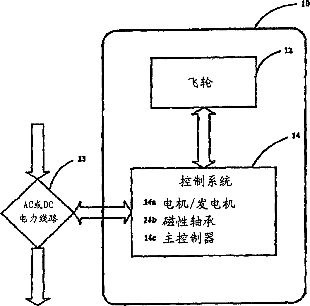
[0019] figure 1 is a block diagram of the system 10 of the present invention. The flywheel assembly 12 is connected to a control system 14 . The control system includes motor / generator power electronics 14a, magnetic bearing controller 14b and master controller 14c. These components can input electrical power from a power line 13 to the flywheel assembly 12 or output electrical power from the flywheel assembly 12 to the power line 13 . Flywheel 12 converts input power from electrical energy to mechanical potential energy. On output, the flywheel 12 converts mechanical energy into electrical energy and supplies it to the control system 14 . The motor / generator power electronics 14a regulates the input and output power to match the power line 13, converting AC to DC or vice versa to match the flywheel voltage to the power line 13 voltage. The magnetic bearing controller 14b monitors the shaft position and uses the magnetic bearing to make adjustments to maintain the motor / ge...


PUM


Abstract

An optimized flywheel energy storage system utilizing magnetic bearings, a high speed permanent magnet motor / generator, and a flywheel member. The flywheel system is constructed using a high strength steel wheel for kinetic energy storage, high efficiency magnetic bearings configured with dual thrust acting permanent magnet combination bearings, and a high efficiency permanent magnet motor generator. The steel wheel provides a cost effective, high speed construction for the energy storage rotor.

Description

technical field [0001] The present invention relates to the field of energy storage devices, and more particularly to a complete electrical energy storage and recovery system through controlled storage and release of kinetic energy. Background technique [0002] US Patent No. 5,614,777 issued March 25, 1997 to Jack G. Bitterly et al discloses and claims a flywheel based energy storage system utilizing an integral motor / generator, high speed flywheel and magnetic bearings. The system described in the '777 patent is costly due to the need for composite rotor materials, inability to minimize power, and the need for an active thrust bearing to provide the force necessary to lift the rotor and maintain active axial position control suspension. Additionally, the patented system does not allow a large motor / generator to provide a large power output in a short period of time. This is due to the structural nature of the motor / generator being placed outboard of the bearings, where t...

Claims


Application Information

Patent Timeline
Patent Type & Authority Applications(China)
IPC IPC(8): H02K7/02H02K7/09H02K1/27
CPCH02K1/2726F16C32/0459F16C2361/55H02K7/09F16C32/0491F16C32/0474H02K7/025Y02E60/16H02K7/02
Inventor 帕特里克·T·麦克马伦科·S·哈因
Owner 帕特里克·T·麦克马伦
Why Eureka
Try Eureka