Technique for manufacturing wearable pipe made from composite bimetal

A manufacturing process and wear-resistant pipe technology, which is applied in the field of bimetal composite wear-resistant pipe manufacturing technology, can solve the problems of high bonding strength of the composite interface and the inability to achieve large-area metallurgical bonding of the two layers of metal in the composite pipe, so as to avoid primary defects , Guarantee the effect of long-distance mobility

Inactive Publication Date: 2006-04-19
XI'AN UNIVERSITY OF ARCHITECTURE AND TECHNOLOGY
View PDF0 Cites 26 Cited by
  • Summary
  • Abstract
  • Description
  • Claims
  • Application Information

AI Technical Summary

Problems solved by technology

[0003] The purpose of the present invention is to provide a manufacturing process of bimetallic composite wear-resistant pipes, which can produce bimetallic composite wear-resistant pipes of different shapes and specifications such as straight pipes, bent pipes, and tees, and solve the problem of the two-layer metal wear-resistant composite pipe. The problem that large-area metallurgical bonding cannot be realized between them makes the composite interface have high bonding strength and strong thermal shock resistance. For local parts with severe wear, eccentric composite and thickened composite can be achieved, and thin-wall composite wear-resistant pipes can also be realized. Production

Method used


Image

  • Technique for manufacturing wearable pipe made from composite bimetal
  • Technique for manufacturing wearable pipe made from composite bimetal
  • Technique for manufacturing wearable pipe made from composite bimetal

Examples


Embodiment 1

[0048] Example 1: Manufacture of bimetal composite elbow

[0049] Refer to the process flow Figure 5 . Manufacturing process of the present invention is carried out according to the following steps:

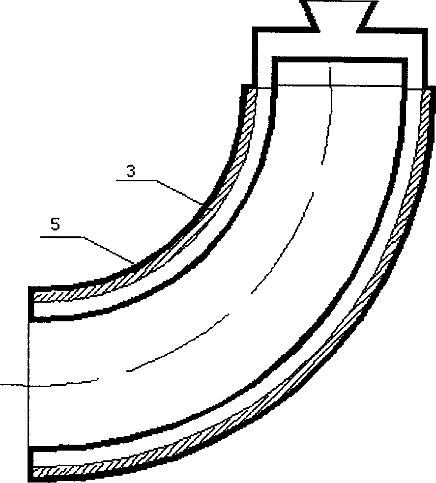
[0050] a. Use an A3 steel seamless straight pipe with an inner diameter of Φ133mm to make the outer casing 3 by heat-bending, with a radius of curvature of 600mm and a central angle of 90 degrees.

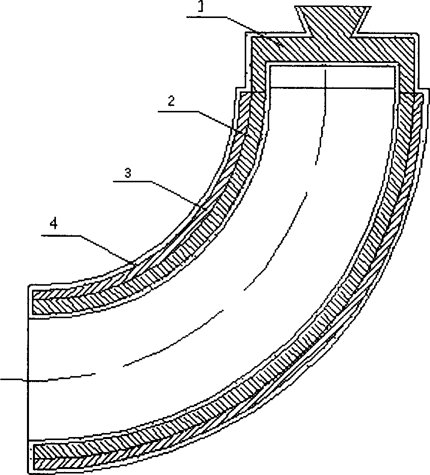
[0051] b. Cut the polystyrene foam block into the lost foam 2 in the shape of the inner liner with a heating wire. The outer diameter of the lost foam 2 is equal to the inner diameter of the outer sleeve 3, the thickness is 8mm, and the radius of curvature and the central angle are the same as the outer sleeve 3 are equal. refer to figure 1 .

[0052] c. Cut the polystyrene foam block into the shape of the gating system with a heating wire, and fix it to the inner liner lost foam 2 by bonding it with white latex. refer to figure 1 .

[0053] d. Prepare the coating and put it ...

Embodiment 2

[0061] Embodiment 2: Manufacture bimetal composite wear-resistant tee pipe

[0062] Refer to the process flow Figure 5 . Manufacturing process of the present invention is carried out according to the following steps:

[0063] a. Weld the 16Mn steel seamless straight pipe with an inner diameter of Φ219mm to make the three-way outer casing 3 .

[0064] B. Cut the polystyrene foam block into the lost foam 2 of the liner pipe shape with the electric heating wire. The outer diameter of the lost foam 2 is equal to the inner diameter of the outer sleeve, and the thickness is 12mm. The length of each part is equal to the three-way outer sleeve. The method of filling is used to make the lost foam of the lining seamless at the tee joint.

[0065] c. Cut the polystyrene foam block into the shape of the gating system with a heating wire, and fix it to the inner liner lost foam 2 with white latex glue 1 .

[0066] d. Prepare the paint and put it into the paint pool. The paint formula...


PUM

PropertyMeasurementUnit
particle sizeaaaaaaaaaa

Abstract

A technology for manufacturing the antiwear bimetal tube includes such steps as providing an ordinary steel tube as external sleeve tube, installing a consumable mold made of foam polystyrene plastics in it, installing pouring system to it, dipping paint and adhering sand several times to form a shell, high-temp calcining for gasifying said plastics and preheating steel tube, pouring molten antiwear alloy, and cooling.

Description

technical field [0001] The invention relates to a manufacturing process of conveying pipes in metallurgy, mining, electric power, petroleum, construction, coal and other industries, in particular to a manufacturing process of bimetal composite wear-resistant pipes. Background technique [0002] In metallurgy, mining, electric power, petroleum, construction, coal and other industries, materials are transported through pipelines under pressure, and the pipelines are subjected to high pressure and severe wear, which brings very large economic losses to related enterprises. Pipelines made of a single material cannot achieve the harmony of various mechanical properties such as wear resistance-weldability-impact resistance, and the overall performance is poor and cannot meet the actual application conditions. Modern composite theory and technology must be introduced to combine Combining materials with different physical properties can reflect the highest performance of various com...

Claims


Application Information

Patent Timeline
Patent Type & Authority Applications(China)
IPC IPC(8): B22D19/16B22D19/08
Inventor 许云华岑启宏
Owner XI'AN UNIVERSITY OF ARCHITECTURE AND TECHNOLOGY
Why Eureka
Try Eureka