Method and device for multiplexing and demodulating sensor based on optical fiber grating in long cycle

A technology of fiber grating and demodulation method, applied in the field of optical fiber sensing, can solve the problems of multiplexing and demodulation method of LPGP that no one has proposed

Inactive Publication Date: 2006-04-19
ZHEJIANG UNIV
View PDF0 Cites 17 Cited by
  • Summary
  • Abstract
  • Description
  • Claims
  • Application Information

AI Technical Summary

Problems solved by technology

For the same reason, so far, no one has proposed an effi

Method used


Image

  • Method and device for multiplexing and demodulating sensor based on optical fiber grating in long cycle
  • Method and device for multiplexing and demodulating sensor based on optical fiber grating in long cycle
  • Method and device for multiplexing and demodulating sensor based on optical fiber grating in long cycle

Examples


Embodiment Construction

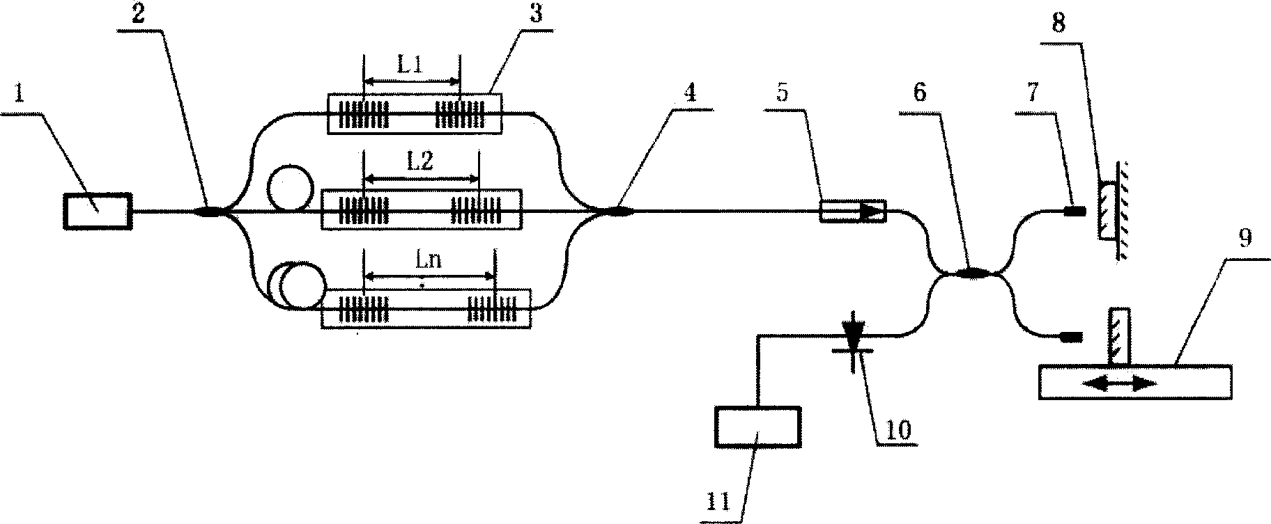
[0018] Such as figure 1 As shown, the input ends of multiple parallel-connected LPGP sensors 3 with different grating center distances are respectively connected to the optical signal of the broadband light source 1 through the optical fiber coupler 2 , and the output end is connected to the optical signal of another optical fiber coupler 4 . Optical one-way isolator 5 input end is connected with optical signal of fiber coupler 4, and its output end is connected with the input end of photodiode 10 and one end optical signal of 3-dB fiber optic coupler 6, and the output end of photodiode 10 is connected with data The acquisition card 11 is electrically connected. The other end of the 3-dB fiber optic coupler 6 is respectively connected to the optical signals of two fiber collimators 7, and two mirrors 8 are arranged corresponding to the positions of the two fiber collimators 7, one of which is controlled by a stepping motor 9 Its position moves. The above-mentioned multiple L...


PUM


Abstract

Fiber optic coupler averagely distributes light intensity of light source in wide band into multiple LPGPs possessing different path differences. Multiplex is accomplished after each path of signal light is converged. Through a light unidirectional isolator, multiplex signal light enters into 3-dB fiber optic coupler. Through collimator of optical fiber, two beams of signal light are sent to reflector, and reflective back to optical fiber. Controlling position movement of one reflector compensates phase difference introduced by LPGPs in different path differences. Compensated two paths of optical signal are converged and intervened at 3-dB fiber optic coupler. The intervened pattern is converted to electrical signal by photo diode; and the signal is collected by data collection card so as to complete demodulation. Advantages are: low cost, suitable to integration and combined to instrument.

Description

technical field [0001] The invention belongs to the technical field of optical fiber sensing, and in particular relates to a method for multiplexing and demodulating signals of long-period optical fiber gratings to sensors and equipment for realizing the method. Background technique [0002] In the field of optical fiber sensing, the long-period grating pair (LPGP) has become a very important sensing device in the industry due to its sensitivity to microbending, temperature, stress, and refractive index changes, especially for liquids. High-precision measurement of refractive index. Use the first long-period fiber grating to couple half of the light energy in the fiber core layer to the fiber cladding layer, and then couple it back to the core layer by the second grating after a certain distance of propagation, and merge with the other half of the light passing through the core layer. The grating pair actually constitutes a Mach-Zehnder (M-Z) interferometer with the fiber c...

Claims


Application Information

Patent Timeline
IPC IPC(8): G01D5/353G01N21/41
Inventor 管祖光何赛灵
Owner ZHEJIANG UNIV
Why Eureka
Try Eureka