Ceramic co-fired type common mode filter and its making method

A common-mode filter and co-firing technology, which is applied to waveguide devices, inductors, fixed inductors, etc., can solve the problems of high differential-mode impedance, low cost, and large signal loss, achieving reduced impedance value and excellent performance , the effect of high impedance values

Inactive Publication Date: 2006-04-26
INPAQ TECH
View PDF0 Cites 1 Cited by
  • Summary
  • Abstract
  • Description
  • Claims
  • Application Information

AI Technical Summary

Problems solved by technology

[0002] There are two main types of common-mode filters in the prior art, which are laminated and wire-wound. Wire-wound filters have better electrical properties, but their cost is high and their output is small, so they cannot be widely used in electronic products. application
And the multilayer common mode filter 10 (as shown in Fig. 1 and figure 2 As shown), the inner electrode 11 is partly covered with magnetic material 12, so its cost is low and it can be mass-produced, but its electrical properties are worse than those of the wire-wound type, mainly because the impedance in the differential mode cannot be effectively reduced to a special Specification requirements, such as USB2.0 and IEEE1394, so electronic application engineers cannot have products with good electrical performance and reasonable price, which makes the application of common mode filters not very wide
[0003] At present, the production method of the prior art still stays at the stage of making a common mode filter with iron oxide, and the electrical diagram is as follows figure 2 As shown, the differential-mode impedance of the signal application frequency band is high in special specifications, such as the USB2.0 specification, the signal frequency band is between 48 and 480MHz, and the signal has considerable loss when passing through the common-mode filter, which makes the signal reception The terminal cannot effectively process the signal, or even receive the signal, and the impedance difference between the common mode and the differential mode is small, which cannot meet the electrical requirements of passing the signal and suppressing the noise.
[0004] It can be seen that there are still many electrical defects in the filter of the prior art, so it is urgent to improve

Method used


Image

  • Ceramic co-fired type common mode filter and its making method
  • Ceramic co-fired type common mode filter and its making method
  • Ceramic co-fired type common mode filter and its making method

Examples


Embodiment Construction

[0019] Relevant detailed content and technical description of the present invention, now in conjunction with accompanying drawing, explain as follows:

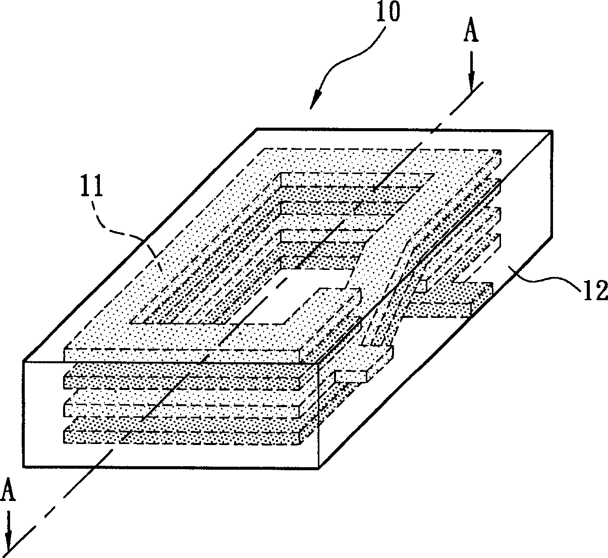
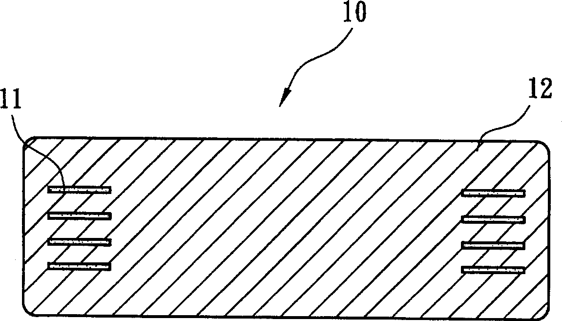
[0020] Please also see Figure 3-1 and Figure 3-2 As shown, they are respectively a three-dimensional schematic diagram and a cross-sectional view of the structure of the ceramic co-fired common mode filter of the present invention. As shown in the figure, the ceramic co-fired common mode filter 20 of the present invention is a coil-shaped inner electrode 21 and Two or more materials such as non-magnetic material 23 and magnetic material 22 are co-fired, and different parts of the components are selected according to the electrical requirements, and different materials are prepared according to the powder characteristics of the materials. Appropriate operability, so that the ceramic co-fired common-mode filter 20 of the main body is completed by co-firing through the special sintering curve that is produced together in each ...


PUM


Abstract

The invention discloses a ceramic co-sinter co-mode filter to overcome the defect of laminated or winding filter. Wherein, selecting proper materials of different electrical property according to different demand of parts of element, adjusting proper operation by material powder character to integrate together, then completing the element main body with special sintering curve and co-sinter method, finally, obtaining the objective filter.

Description

technical field [0001] The present invention relates to a ceramic co-fired common-mode filter and a manufacturing method thereof, in particular to a method of using different electrical properties of different materials to select suitable materials for different parts of the element according to electrical requirements, and to Different materials are prepared according to the powder characteristics of the material, so that they are produced together in each process, and then the ceramic co-fired common mode filter and its main body are completed by co-firing through the researched special sintering curve. Production Method. Background technique [0002] There are two main types of common-mode filters in the prior art, which are laminated and wire-wound. Wire-wound filters have better electrical properties, but their cost is high and their output is small, so they cannot be widely used in electronic products. application. And the multilayer common mode filter 10 (as shown i...

Claims


Application Information

Patent Timeline
Patent Type & Authority Applications(China)
IPC IPC(8): H01F17/00H01P1/20H03H1/00
Inventor 钟祥文
Owner INPAQ TECH
Why Eureka
Try Eureka