

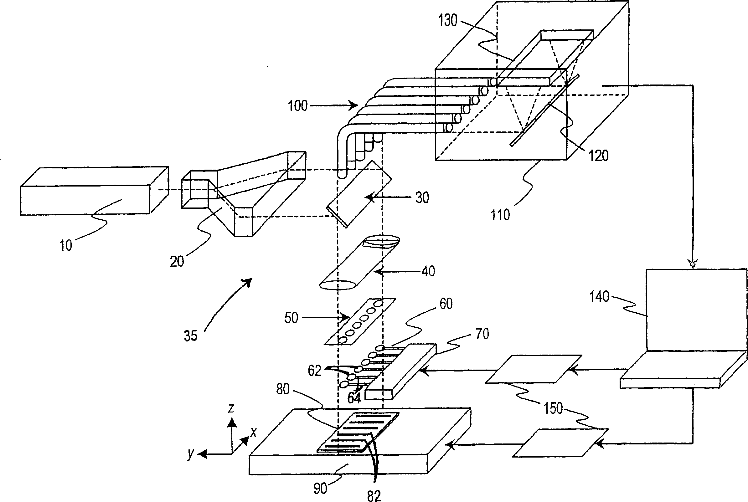
Method and apparatus for enhanced nano-spectroscopic scanning
A nano-lens technology, applied in the field of nano-spectral scanning, can solve the problems that have not been disclosed or proposed, and have not been proposed to read out multiple samples in parallel
- Summary
- Abstract
- Description
- Claims
- Application Information
AI Technical Summary
Problems solved by technology
Method used
Image

Examples
Embodiment Construction
[0036] I. Definition
[0037] The following terms have the following meanings, unless otherwise stated, "plasmon resonance metal" includes any metal, such as gold, silver or aluminum, which can support surface electromagnetic modes - surface plasmon polarization (SPP), i.e. photons and plasmons Coupling modes of bulk oscillators.
[0038] A "chemical group" in a sample may include a subunit or part of a subunit in a polymer, such as a nucleic acid group, or a chemically substituted molecular group, such as a hydroxyl, amine, alkyl, acid or aldehyde group. These chemical groups are characterized by characteristic enhanced Raman spectral signatures or features.
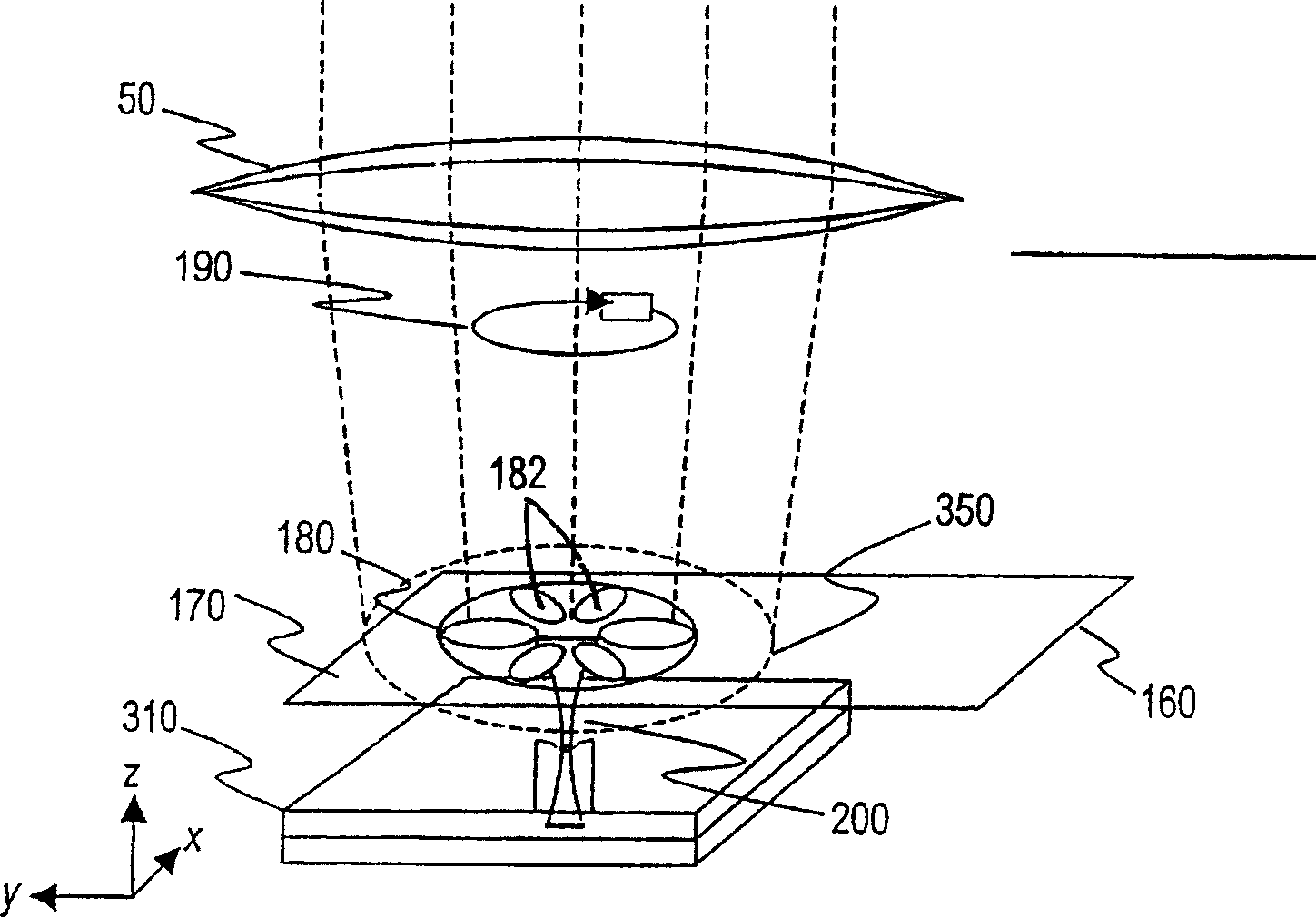
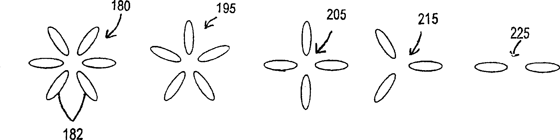
[0039] "Gap mode" refers to electromagnetic conventional modes or electromagnetic eigenmodes that are placed near a metal surface by an external electromagnetic field located in the gap between two or more plasmon resonant particles (less than 40nm), especially when the plasmon resonance is excited on the metal surf...
PUM
| Property | Measurement | Unit |
|---|---|---|
| size | aaaaa | aaaaa |
| diameter | aaaaa | aaaaa |
Abstract
Description
Claims
Application Information