

Centrifugal compressor and manufacturing method for impeller
A centrifugal compressor and impeller technology, applied in mechanical equipment, machines/engines, liquid fuel engines, etc., can solve the problems of reduced impeller efficiency or performance, reduced compressor efficiency, reduced flow range, etc. The effect of reduced variation and increased flow range
- Summary
- Abstract
- Description
- Claims
- Application Information
AI Technical Summary
Problems solved by technology
Method used
Image

Examples
Embodiment 1
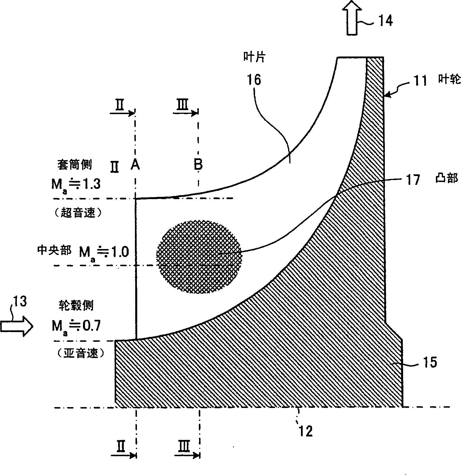
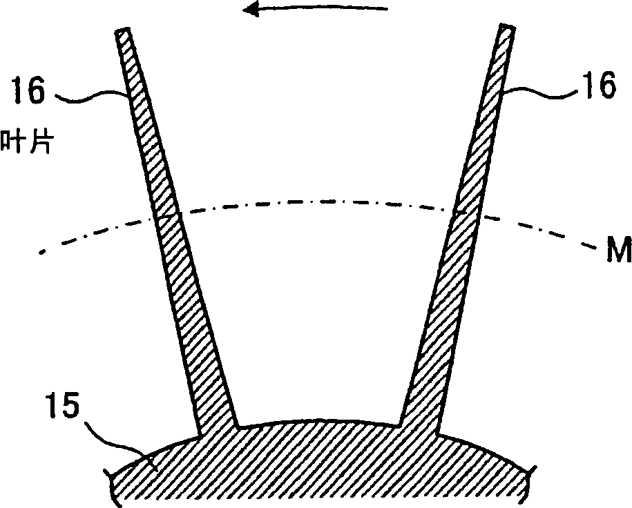
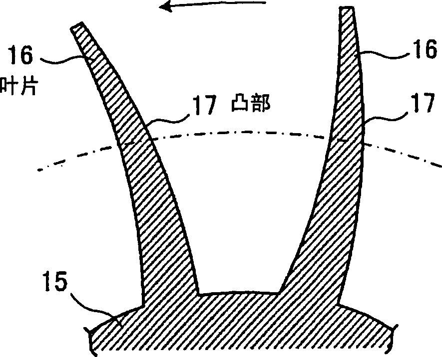
[0062] figure 1 It is a sectional view of main parts of the centrifugal compressor of Embodiment 1 of the present invention, figure 2 yes figure 1 II-II sectional view, image 3 yes figure 1 Section III-III, Figure 4 is a schematic diagram of the impeller of the centrifugal compressor of Embodiment 1, Figure 5 It is a schematic diagram showing the manufacturing method of the impeller of the centrifugal compressor of Example 1, Image 6 It is a schematic diagram showing the processing procedure of the impeller, Figure 7 It is a schematic diagram showing the shape of the central part of the blade of the impeller of Example 1, Figure 8 It is a graph showing the flow rate per unit area corresponding to the relative inflow velocity of the fluid in the centrifugal compressor of Example 1.
[0063] The centrifugal compressor of this embodiment is as Figure 1 to Figure 4 As shown, an impeller 11 is rotatably supported by a rotating shaft 12 in a casing (not shown), an...
Embodiment 2
[0075] Figure 9 It is a sectional view of main parts of a centrifugal compressor according to Embodiment 2 of the present invention, Figure 10 yes Figure 9 The X-X profile, Figure 11 is a schematic diagram of the impeller of the centrifugal compressor of Embodiment 2, Figure 12 It is a schematic diagram showing the manufacturing method of the impeller of the centrifugal compressor of the second embodiment. In addition, the same symbols are used for members having the same functions as those described in the above-mentioned embodiments, and overlapping descriptions will be omitted.
[0076] In the centrifugal compressor of embodiment 2, such as Figure 9 to Figure 11 As shown, the impeller 31 has a plurality of blades 34 radially fixed to the outer peripheral portion of a hub 33 fixed to the rotating shaft 32 . On the negative pressure surface of the vane 34 of the impeller 31, a convex portion 35 is formed in a curve (arc shape) from the front edge portion A to the s...
Embodiment 13
[0083] Figure 13 It is a cross-sectional view of an impeller of a centrifugal compressor according to Embodiment 3 of the present invention. In addition, the same symbols are used for components having the same functions as those described in the above-mentioned embodiments, and overlapping descriptions will be omitted.
[0084] In the centrifugal compressor of the present embodiment, as Figure 13 As shown, the impeller 41 is constituted by making the hub side concave when using either the convex portion 17 of the impeller 11 of the first embodiment or the peak-shaped convex portion 35 of the impeller 31 of the second embodiment. That is, in the impeller 41 of the present embodiment, the convex portion 17 is formed so as to gradually become convex from the negative pressure surface of the impeller 16 toward the slit portion, or on the negative pressure surface of the blade 34, the convex portion 17 is gradually formed from the leading edge portion to the slit portion. The ...
PUM
 Abstract
Description
Claims
Application Information